GENERAL INFORMATION

Early built M300 and M375 Motor Home chassis are equipped with vacuum hydraulic power brakes, as follows:

  • M300 Models: These models use a daul hydraulic system and two 8 inch (outside diameter) Midland C-490G booster units, one for each system. Figure 1 shows location and brake line and hose routing.
  • M375 Models: These models use a single hydraulic system and one 11-1/2 inch (outside diameter) Midland C-464R booster unit. Figure 2 shows location and brake line and hose routing.

The principles of operation and applicable service procedures for the power brake units used on Motor Home chassis are virtually identical except for certain minor details. Both the C-490G and C-464R booster units are single diaphragm vacuum booster units made up of three basic functional components; the power section, the hydraulic slave cylinder and the vacuum control valve. A disassembled view of a typical single diaphragm booster unit is shown in Figure 3.

  1. The power section consists of two disc metal sections separated by a pressure plate and rubber diaphragm assembly held together by a clamp strap. The diaphragm acts as a seal between the two sections of the booster chamber. A push rod attached to the pressure plate extends through a support bushing seal into the hydraulic slave cylinder and actuates the slave cylinder piston when the pressure plate moves forward for brake application.
  2. The power section push rod is attached to the hydraulic slave cylinder which contains a piston cup and piston return spring. The piston has a spring-loaded check valve which automatically controls fluid through the center of the piston and cup.
  3. The power section is actuated by the vacuum control valve, located on the top of the hydraulic slave cylinder. The upper seat seals off atmospheric pressure and the lower seat seals oiT the passage to the front chamber and manifold vacuum pressure.

C-490G

M-300


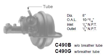
C-490G
Also known as Hypower Boosters
Precision Rebuilders, Inc.
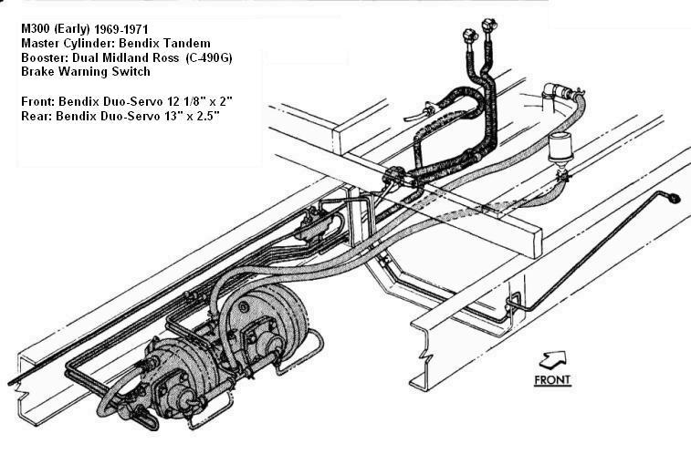

Figure 1

M-375


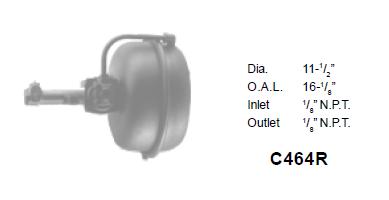
C-464R
Also known as Hypower Boosters
Precision Rebuilders, Inc.
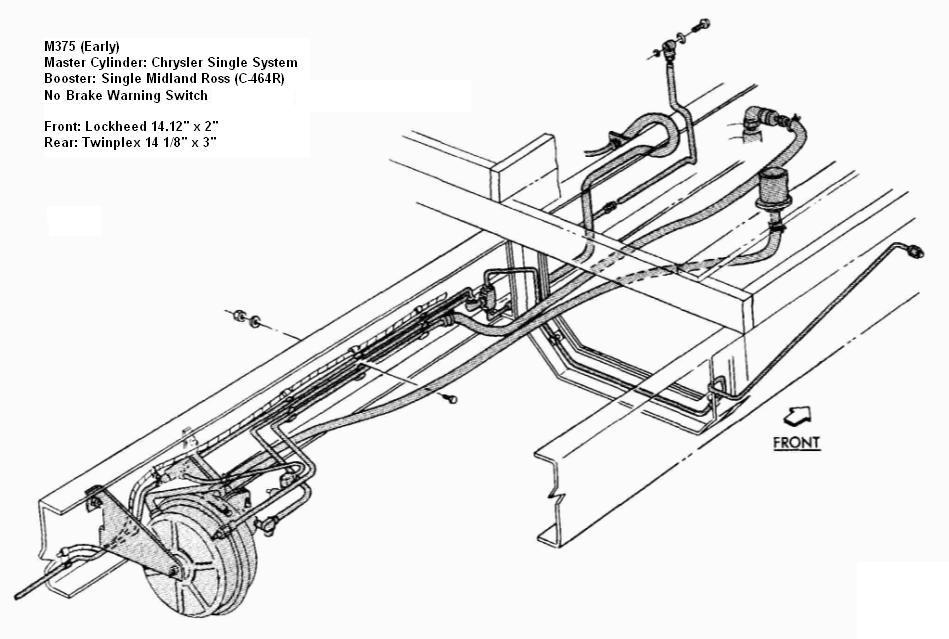

Figure 2

Figure 1

SYSTEM TESTS FOR LEAKAGE

  1. Depress the brake pedal, apply full pressure. Hold the pedal in this position and start the engine. The pedal should then move downward. If it does not, remove the pipe plug from the rear section of the booster chamber and install a vacuum gauge. Start the engine and check the vacuum gauge—it should read from 16 to 21 inches of vacuum. If the vacuum gauge reading is normal, the booster unit is defective.
  2. Depress the brake with the engine running. The vacuum gauge should read zero. If it does not, the control valve is malfunctioning.
  3. lf the gauge reading indicates that the control valve is functioning, again depress the brake pedal to obtain a zero reading on the vacuum gauge. Hold the brake pedal in this position for one minute. Any downward movement of the brake pedal during this period indicates a iiuid leak in the hydraulic system. Any upward pedal movement in this test indicates a fluid leak past the slave cylinder piston check valve.
  4. With the engine running, depress the brake pedal with sufficient pressure to show a zero reading on the vacuum gauge. Shut engine off while maintaining pedal pressure. Hold the pedal in this position for one minute. A pedal kick-back indicates a vacuum leak which may be in the manifold check valve, vacuum lines or in the booster unit itself. Perform Test 5 before attempting to locate the leak.
  5. Start the engine to create vacuum in the system but do not operate brakes. Shut engine off and watch vacuum gauge. Vacuum should drop off at a rate not to exceed one inch per minute. If leakage is indicated in Test 4 but not in Test 5, the booster unit is at fault. If leakage is indicated in both tests, the trouble may be in the manifold check valve, the vacuum line or in the booster unit itself.

If in-vehicle tests and inspection show that the vacuum booster unit is the cause of brake system malfunction, the vacuum booster must be removed for service or reconditioning.

SERVICE DIAGNOSIS

Condition Possible Cause Correction

VACUUM LEAK

(Booster in Released Position)
  1. End plate, center plate or control valve body gaskets leak.
  2. End plate distortion.
  3. Control valve poppet misaligned.
  4. Loose vacuum cylinder bolts.
  5. Loose control valve body screws.
  6. Large control valve poppet spring not centered in spring retainer.
  1. Recondition booster unit.
  2. Replace end plate.
  3. Disassemble, clean and reassemble correctly.
  4. Coat vacuum cylinder bolts lightly with a suitable sealing compound and tighten to specified torque.
  5. Tighten control valve body screws to specified torque.
  6. Disassemble unit and reassemble.

VACUUM LEAK

(Booster in Applied Position)
  1. Leak at control valve poppet and seat.
  2. Dry or faulty piston leather packing.
  3. Faulty control valve diaphragm assembly.
  1. Clean and inspect poppet and seat for damage and repair as necessary.
  2. Clean and lubricate piston leather or replace.
  3. Replace faulty parts.

EXTERNAL HYDRAULIC LEAKS

  1. Gasket ("O" ring) leaking at end plate joint.
  2. Fluid leaking at copper gasket under hydraulic cylinder end cap.
  1. Disassemble, clean and replace ("O" ring) gasket and reassemble.
  2. Remove end cap and inspect copper gasket and seat. Install new copper gasket.

INTERNAL HYDRAULIC LEAK AT LOW PRESSURES

  1. Control valve hydraulic piston cup failure.
  2. Faulty push rod seal.
  1. Recondition control valve unit.
  2. Replace push rod seal.

INTERNAL LEAKS AT HIGH PRESSURE

  1. Fluid passing copper gasket under hydraulic fitting in control valve.
  2. Inspect cups and seals of master cylinder for cuts and scores.
  3. Inspect cups of control valve hydraulic piston.
  1. Clean and inspect gasket and fitting. Replace if faulty.
  2. Hone master cylinder and replace cups and seals.
  3. Replace faulty cups.

HYDRAULIC PRESSURE BUILDUP

(Without Added Input)
  1. Check hydraulic piston check valve and slot for foreign material under valve.
  1. Clean or replace valve and seats as condition indicates.

FAILURE TO RELEASE

  1. Weak vacuum cylinder piston return spring.(b) Dry vacuum piston leather packing.
  2. Swollen rubber cups caused by inferior or contaminated brake fluid.
  3. Darnaged or dented vacuum cylinder she .
  4. Dirty or sticky control valve.
  5. Dirt, rust or foreign mattér in any system component.
  1. Replace vacuum cylinder piston return spring.
  2. Lubricate vacuum piston leather packlng.
  3. Flush hydraulic system and recondition or replace all cylinders.
  4. Replace vacuum cylinder shell.
  5. Recondition control valve assembly.

FAILURE OF BOOSTER TO OPERATE WITHIN SPECIFIED PRESSURES

  1. Rusty, dirty or distorted vacuum cylinder shell.
  2. Dry or worn vacuum cylinder leather packing.
  3. Swollen rubber cups caused by inferior brake fluid.
  4. Worn or scored hydraulic cups.
  5. Dirt, rust or foreign matter in any system component.
  1. Clean or replace vacuum cylinder shell.
  2. Reconditlon and lubricate vacuum booster.
  3. Reconditlon master cylinder. Replace brake fluid.
  4. Reconditlon master cylinder.
  5. Reconditlon and lubricate the brake booster assembly.

LOSS OF FLUID

  1. Fluid leaking past cup in master cylinder.
  2. Brake wheel cylinders leaking.
  3. Loose hydraulic hose connections.
  4. Leaking stop light switch.
  1. Recondition or replace master cylinder.
  2. Recondition or replace wheel cylinders.
  3. Inspect and tighten all hydraulic connections.
  4. Replace stop light switch.

PRESENCE OF BRAKE FLUID ON VACUUM CYLINDER

  1. Piston cup or push rod leaking.
  1. Recondition master cylinder.

PEDAL KICKS BACK AGAINST FOOT WHEN BRAKES ARE APPLIED

  1. Vacuum leakage.
  2. Dirt under control valve or damaged seat
  3. Weak or broken spring.
  1. Inspect and correct vacuum leak.
  2. Clean and recondition booster assembly.
  3. Replace spring.

BRAKES ARE SLOW TO RELEASE

(Note: First jack up Motor Home and determine whether or not brakes are dragging)
  1. Incorrect pedal linkage adjustment.
  2. Compensating port of master cylinder plugged.
  3. Brake shoes sticking.
  4. Weak brake shoe return spring.
  5. Booster control valve piston sticking.
  6. Booster air filter clogged.
  7. Control valve diaphragm return spring missing.
  8. Defective check valve in slave cylinder piston.
  9. Dirt under atmospheric valve disc.
  1. Adjust and lubricate pedal linkage.
  2. Clean master cylinder with compressed air.
  3. Free up and lubricate brake shoes.
  4. Replace brake shoe return spring.
  5. Clean booster control valve piston and Iubricate.
  6. Clean air filter in mineral spirits.
  7. Install new control valve return spring.
  8. Recondition slave cylinder piston.
  9. Clean atmospheric valve.

ENGINE RUNS UNEVENLY AT IDLE WITH BRAKES RELEASED

  1. Vacuum leakage.
  2. Dirt under control valve disc or damaged seat.
  3. Defective spring.
  1. Inspect and tighten all vacuum fittings.
  2. Clean or replace control valve.
  3. Replace defective spring.

ENGINE RUNS EVENLY AND PEDAL IS HARD WITH BRAKES APPLIED

  1. Control valve piston assembly not seating on vacuum disc.
  2. Defective control valve plate and diaphragm.
  3. Defective pressure plate and diaphragm.
  1. Clean or replace control valve assembly.
  2. Replace control valve plate and diaphragm.
  3. Replace pressure plate and diaphragm.

BRAKE PEDAL IS HARD AT DIFFERENT INTERVALS

  1. Defective manifold check valve.
  2. Slave cylinder piston sticking from inferior brake fluid.
  3. Brake booster air cleaner clogged.
  1. Clean or replace manifold check valve.
  2. Clean and recondition slave cylinder.
  3. Clean air cleaner in mineral spirits and blow dry with compress air.

BENCH SERVICE PROCEDURES

Removal (Figure 4)

  1. Depress the brake pedal several times to remove all vacuum from the system.
  2. Loosen air inlet hose clamp and disconnect the air inlet hose.
  3. Disconnect the hydraulic line from the master cylinder at the booster.
  4. Disconnect the vacuum line hose at the booster.
  5. Disconnect the hydraulic line from the booster hydraulic outlet.
  6. Remove the vacuum booster mounting bracket bolts and lift booster from the frame. Place on bench for further service.

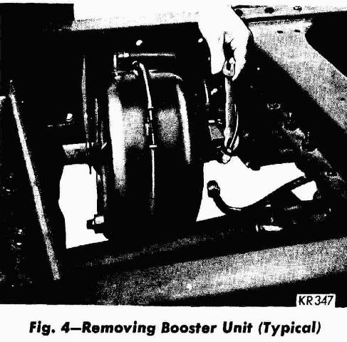
Figure 4 - Removing Booster Unit

(Disassembly)

The following bench service procedures are applicable to both the Midland C-490G and C-464R single diaphragm brake boosters.

  1. Remove large plug at end of slave cylinder.
  2. Remove copper washer, springs and retainer.
  3. Scribe both sections of power chamber and punch-mark iianges of control valve and slave cylinder. Scribe lines and punch marks must be opposite each other so the components can readily be assembled in their original positions.
  4. Remove the control valve-to-power chamber by-pass tube and seal.
  5. Remove clamp ring, rear section of power chamber, diaphragm and pressure plate assembly with return spring.
  6. Unscrew push-rod bushing from power chamber front and slave cylinder body and separate chamber and slave cylinder. Remove gasket and seals.
  7. Remove four screws holding valve cover to control valve and remove cover.
  8. Remove four screws from control valve body. Lift control valve body diaphragm return spring, control valve piston and diaphragm assembly from slave cylinder body.
  9. Remove screw and washer that holds the vacuum disc spring and atmospheric valve disc together. Replace spring if it is rusty.
  10. Push slave cylinder piston and piston cup out of the front end of the slave cylinder with a 1/4 inch by 12 inch rod.

CLEANING AND INSPECTION

Wash all metal parts in alcohol. Wipe thoroughly with clean cloth and dry all internal passages with compressed air. Inspect parts and replace all which are worn or damaged. Check front and rear chamber sections for dents. A dented chamber body can cause brakes to fail to release. Inspect the slave cylinder body. If there is any evidence of corrosion in either the slave cylinder bore or control valve bore, the slave cylinder body should be replaced. The push-rod must be perfectly smooth to prevent seal damage and leaks. Replace if rough or damaged. Never grind off push-rod end. If the control valve disc assembly is pitted or damaged, replace with new disc assembly and spring. Disassemble the slave cylinder piston assembly and clean it thoroughly to insure proper check valve operation. The slave cylinder piston assembly should not require replacement unless a definite hydraulic leak was evident before disassembly or a major overhaul is being performed. If a leak was evident, replace piston assembly rubber cup and control piston cup. Always replace the control valve diaphragm, all rubber cups, seals, and spring during reassembly.

Reassembly

  1. Reassemble control valve diaphragm (seals, plunger, diaphragm and seat). Be sure that the diaphragm beads faces away from the plunger. Coat piston seals with brake fluid and insert ssembly into control valve bore.
  2. Install seat in control valve body. Reassemble control valve disc assembly with small end of spring resting on vacuum valve disc. Secure discs with screw and washer and install in valve body.
  3. Place diaphragm spring in valve body with small end resting on diaphragm.
  4. Put control valve body in position on slave cylinder, align punch marks and install four hold down screws. Tighten securely. Install control valve cover.
  5. Place "O" ring on tube in power chamber front section. Install gasket on slave cylinder body.
  6. Install seals in push-rod bushing with seal lip toward slave cylinder end.
  7. Place slave cylinder in vise. Coat all seals with brake fluid and insert push-rod bushing through front section of power chamber from inside of chamber. Thread bushing on the slave cylinder body and tighten to 60-80 foot-pounds torque.
  8. Insert push-rod through center of diaphragm and pressure plate assembly. Secure push rod as close to threaded end as possible. Coat threads with sealing compound, install push-rod nut and tighten securely.
  9. Install diaphragm return spring over push-rod and insert push-rod into bushing and slave cylinder. Be careful not to damage seals. Position diaphragm return spring end over push-rod bushing.
  10. Inspect seal in rear section of power chamber. Replace if necessary. Install plug.
  11. Install by-pass tube loosely in control valve body. Place clamp ring loosely over edge of front chamber.
  12. Place rear section of power chamber over diaphragm and pressure plate assembly. Line up scribe marks, engage by-pass tube in fitting and tighten clamp ring. Tighten by-pass tube fittings.
  13. Dip slave cylinder piston assembly in brake fluid and insert into slave cylinder bore with piston open end facing chamber body.
  14. Dip slave cylinder cup in brake fluid and insert in slave cylinder bore with lip facing open end of cylinder. Insert spring retainer into piston return spring and place in slave cylinder bore.
  15. Install a new copper washer on end plug. Thread end plug into slave cylinder body and tighten securely.

Bleeding The Hydraulic System (With Vacuum Hydraulic Boosters)

Before bleeding hydraulic system on chassis equipped with vacuum brake boosters, the vacuum must be completely eliminated from the booster system. Disconnect manifold tube at booster side of manifold check valve (engine stopped).

CAUTION: When air pressure brake bleeding equipment is used, do not apply more than 25 to 35 pounds of pressure.

A piston stop is provided in the slave cylinder to prevent damage to the return spring while bleeding the brakes. This damage can occur only when the brakes are bledwith vacuum present in the booster system.

WARNING: Do not lubricate diaphragm type boosters.