Dave's Place
Dodge Motorhome Manual Information
PLEASE BE PATIENT, PAGE UNDER CONSTRUTION
|
|
Combination Metering Valve / Brake Warning Switch |
|
GENERAL INFORMATIONAll models with dual master cylinders will have a hydraulic system control valve or brake warning switch mounted on the frame rail behind the master cylinder. Models with disc brakes have a Brake Warning Switch Valve and Metering Valve combined in a single unit (Fig. 1). Models with drum brakes only will have a brake warning switch. |
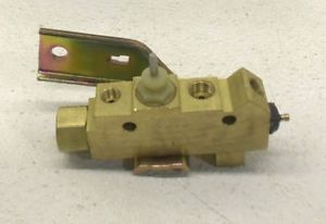 Figure 1 |
SERVICE PROCEDURESCOMBINATION BRAKE WARNING/METERING VALVEThe brake warning switch is used to indicate a failure in either front or rear hydraulic system. The metering valve is used to better balance the hydraulic system during certain braking conditions (Fig. 1). Brake Warning Switch UnitThe brake warning switch used in these combination valves are latching types. If a pressure loss occurs in one side of the dual brake system the piston in the valve will move toward the failed side and latch in that position. This will cause the brake system warning light to come on and stay on until the brake system is repaired. After repairing and bleeding the brake system, applying the brakes with moderate force will hydraulically recenter the piston and automatically turn off the warning light. DO NOT DISASSEMBLE THE VALVE TO RESET THE PISTON. Testing Brake Warning Switch UnitThe brake warning light bulb function can be tested by starting the engine. The light will go on when the ignition key is turned to the extreme right START position and will go off as soon as the engine starts. To test the service brake warning system, raise the car on a hoist and open a wheel cylinder bleeder while a helper depresses the brake pedal and observes the warning light. If the light fails to light, inspect for a burned out bulb, disconnected socket, a broken or disconnected wire at the switch. If the bulb is not burned out and the wire continuity is proven, replace the brake warning switch in the brake line Tee fitting mounted on the frame rail. Metering Valve Unit OperationThe metering valve holds oif hydraulic pressure to the front disc brakes in the 35 to 135 psi range to allow the rear drum brake shoes to overcome the return springs and begin to contact the drums. This feature helps prevent locking the front brakes on icy surfaces under light braking conditions. The metering valve has no effect on front brake pressure during hard stops. Checking Metering Valve
BLEEDING VEHICLES WITH METERING VALVES
|
|
RESIDUAL VALVE |
|
GENERAL INFORMATIONA residual valve is required to maintain light hydraulic pressure in the rear wheel drum brake hydraulic system to keep the wheel cylinder piston cups sealed against the piston bore during "oif brake" periods. Residual valves are located as follows. On RM300 and 1975 M300 models the valve is located in the master cylinder (rear) outlet supplying the rear brakes. On RM350, RM400, M400, M500, and M600 models the valve (formally installed in the front outlet of the master cylinder) is located in the rear brake system outlet of the brake warning metering valve assembly (Fig. 1). SERVICE PROCEDURES |
|
Removal
|
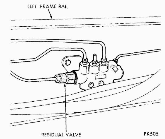 Figure 1 |
Installation
|
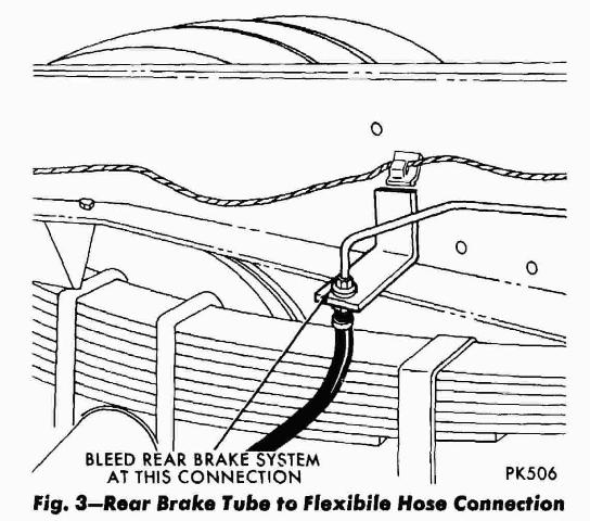 Figure 2 |