**** Engine trys to start but shuts off when ignition key is returned to run position ****
|
|
No voltage at plus (+) terminal of coil when ignition key is in RUN position.
Note:
The fact that the engine tries to start (fires) when the ignition key is in START position indicates that the
Distributor, ECM and coil are working. It also means battery voltage is being applied to the input side of
the Ballast resistor and ECM pin 1.
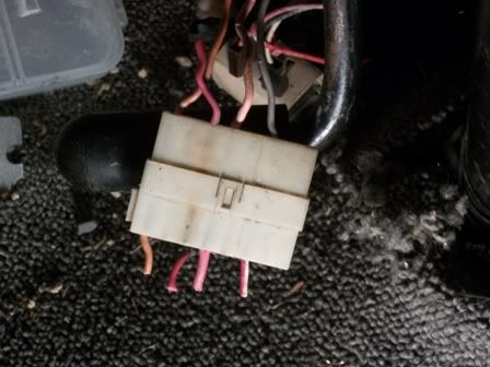
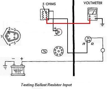
- Verify 12VDC on input side of Ballast Compensating Resistor (Connector with 2 red wires).
- Replace Ballast resistor.
- Compensating Resistor resistance value - 0.5 to 0.6 ohms
|
|
**** Engine will not fire with ignition key in either start or run position ****
|
CAUTION:
Make sure the ignition switch is off when removing or replacing the control unit connector.
Disconnecting the plug from the ECM with the Ignition key ON can damage the ECM module.
- Turn Ignition Switch OFF.
- Remove wiring plug from the Control Unit (ECM).
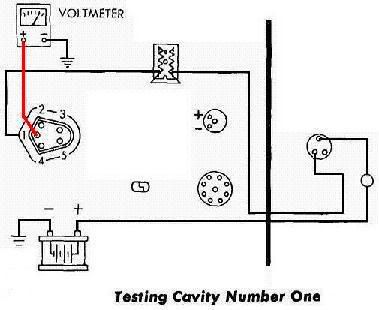
- Ground negative voltmeter lead.
- Connect voltmeter positive lead to the harness connector cavity No. 1.
- Turn Ignition Switch to RUN.
- Verify voltage is within 1 volt of battery voltage with all accessories off.
If correct voltage is present, go to step 36 (problem in wiring path to battery from ECM pin 1) otherwise
continue to next step.
|
|
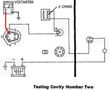
- Connect voltmeter positive lead to the harness connector cavity No. 2.
NOTE:
With connector removed from ECM there is no current following in the circuit. In this condition,
there will not be a voltage drop across the Ballast Compensating Resistor therfore reading a voltage
value within 1 volt of battery votage is normal.
- Verify voltage is within 1 volt of battery voltage with all accessories off. If correct voltage is
present, go to step 16. (coil and compensating resistor OK) otherwise continue to next step.
|
|
- Connect voltmeter positive lead to plus (+) side of coil (Pink wire from Ballast Resistor).
- Verify voltage is within 1 volt of battery voltage with all accessories off.
If voltage is incorrect, go to step 13. (Ballast Resistor circuit problem) otherwise continue to next step.
- Coil is bad, improperly grounded, or wiring between coil and ECM Pin 2 is defective.
- Turn Ignition Switch OFF and repair.
Coil Primary - 1.4 to 1.8 Ohms (plus {+} to minus {-})
Coil Secondary - 8K to 12K Ohms (Center to case ground)
|
|
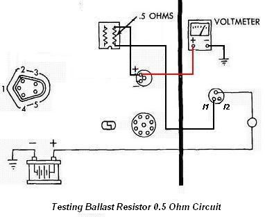
- Connect voltmeter positive lead to input side of Ballast 0.5 Ohm Compensating Resistor (side with 2 pink
wires at one end {output}; red wire on other end {input}).
- Verify voltage is within 1 volt of battery voltage with all accessories off.
- Turn Ignition Switch OFF.
If voltage is correct, either ballast resistor is defective (0.5 Ohm Compensating Resistor) or wiring
between Ballast Resistor and coil is defective.
If voltage incorrect, wiring between ballast resistor and Ignition switch is defective. Repair wiring.
|
|
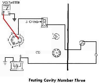
- Connect voltmeter positive lead to the harness connector cavity No. 3.
NOTE:
With connector removed from ECM there is no current following in the circuit. In this condition,
there will not be a voltage drop across the Ballast Compensating Resistor therfore reading a voltage
value within 1 volt of battery votage is normal.
- Verify voltage is within 1 volt of battery voltage with all accessories off.
If correct voltage is present, go to step 21 (AUX resistor OK) otherwise continue to next step.
|
|
- Connect voltmeter positive lead to input side of Ballast 5.0 Ohm Auxilary Resistor (side with dark
green wire at one end {output}; red wire on other end {input}).
- Verify voltage is within 1 volt of battery voltage with all accessories off.
- Turn Ignition Switch OFF.
If voltage is correct, either ballast resistor is defective (5.0 Ohm Aux Resistor) or wiring between
Ballast Resistor and ECM pin 3 is defective.
If voltage incorrect, wiring between ballast resistor and Ignition switch is defective. Repair wiring.
|
|
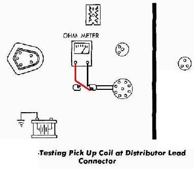
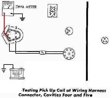
- Turn Ignition Switch OFF.
- Connect one multimeter lead to the harness connector cavity No. 4 and the other multimeter lead to
the harness connector cavity No. 5
- Set Multimeter to read Resistance (Ohms)
- Verify Distributor Pick-up Sensor resistnace is between 350 to 550 Ohms.
If resistance is correct, go to step 28 (1st Distributor Pick-up Sensor check OK) otherwise continue
to next step.
|

|
- Unplug the Pick-up Sensor (lead from Distributor).
- On the Pick-up sensor distributor lead, connect one multimeter lead to one pin in the plug and the
other multimeter lead to the other pin in the plug
- Verify Distributor Pick-up Sensor resistnace is between 350 to 550 Ohms.
If resistance is correct, the wiring from the ECM plug to the distributor plug is defective.
Repair wiring.
If the resistance is incorrect, replace Distributor Pick-up Sensor
NOTE:
If you have a Actron CP9087 Ignition Module and Sensor Testor, perform Sensor Test (Section 2, page
2-46 of the tester manual, Magnetic Reluctance version)
|
|
- Connect one multimeter lead to the harness connector cavity No. 4 and the other multimeter lead to
a good ground
- Verify there is no continuity (open circuit; maximum resistance).
If there is no continuity, go to step 31 (2nd Distributor Pick-up Sensor check OK) otherwise
continue to next step
- Distributor Pick-up Sensor is shorted to ground. Replace Distributor Pick-up Sensor.
|
|
|
NOTE:
If you have a Actron CP9087 Ignition Module and Sensor Testor, perform Sensor Test (Section 2, page
2-46 of the tester manual, Magnetic Reluctance version)
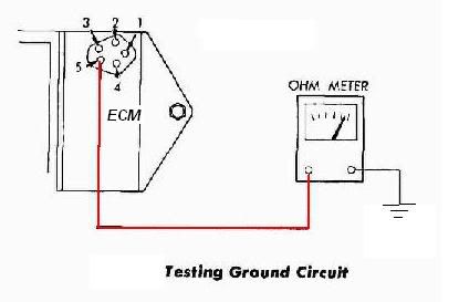
- Connect one multimeter lead to the ECM pin 5 and the other multimeter lead to a good ground
- Verify there is continuity.
If there is continuity, go to step 34 (ECM Ground check OK) otherwise continue to next step.
- Tighten bolts holding ECM module to mounting plate. Retry steps 31 and 32. If there is now
continuity, got to next step, otherwise replace ECM module.
- Reinstall wiring plug to Control Unit (ECM).
- All components and wiring to the ECM module have been verified to be working correctly.
If there is still no spark to the plugs then the problem is one or more of the following:
- Distributor Cap and/or Rotor is defective. Replace Distributor Cap and Rotor.
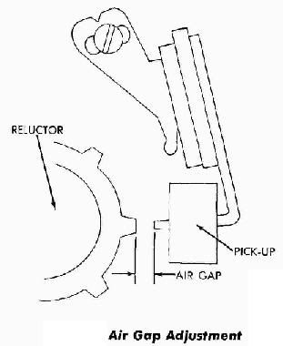
- Distributor Pick-up Air Gap is incorrect. Adjust Distributor Pick-up Air Gap (0.008" Air Gap).
- Distributor Reluctor is damaged. Replace Distributor Reluctor.
- ECM module is defective. Replace ECM module.
NOTE:
If you have a Actron CP9087 Ignition Module and Sensor Testor, perform Control Module Test
(Section 3 using the Magnetic Reluctance Pick-up hookup on page 3-9 of the tester manual)
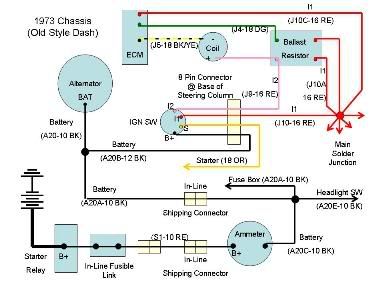
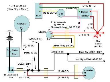
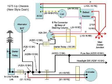
- Turn Ignition Switch OFF.
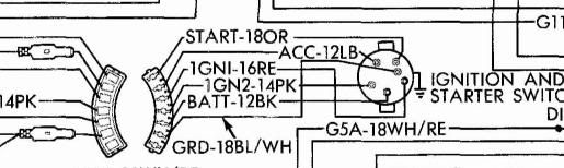
- Using the appropriate drawing below, back track down the battery supply circuit to locate
the bad connection (broken or corroded as applicable).
|
|
|