Dave's Place
The Lost Art of Maintaining a Mopar Distributor
Reformated and updated article:
Hemming Motor News Article - Hemmings Muscle Machines - JANUARY 1, 2007 - BY RAY T. BOHACZ
Back in the day when every spark ignition engine was equipped with breaker points, it was hard enough to find someone who really knew what they were doing when it came to working on a distributor. Today that quest is almost impossible. But if you own a muscle car that was produced prior to 1975, with only a few exceptions, the coil is fired through breakers. Thus, it would behoove those owners to become familiar with the proper service procedures for breaker point ignition systems. This installment of "The Lost Art" series will focus on the Chrysler breaker point and electronic ignition distributor. This style of distributor was used from the early 1960s until the last carburetor equipped V-8 was delivered from a Mother Mopar assembly line.
Back to basics
An ignition system has two basic circuits. The primary, which consists of the breaker points, condenser, ignition switch, and primary windings of the ignition coil. The secondary part of the ignition system includes the secondary windings of the coil, the distributor rotor and cap, along with the spark plug wires and the spark plugs.
The ignition coil can be considered a transformer because it takes the 12 volts supplied by the battery and raises it up to around 30,000 volts. This is required so that the electricity can bridge the gap of the spark plug under cylinder pressure.
The breaker points control the flow of current through the ignition coil and allow the field to build. It can be considered a very accurate on/off switch. When the breakers are closed, the ignition coil is charging (dwell period). When they break open, the field in the coil collapses and induces the higher secondary voltage. On the average V-8 engine the breaker points open and close approximately 150 times per second at 60 mph. Under those conditions the points are closed for around 0.005 of a second for each spark plug firing.
In that brief interval, current has flowed through the coil primary, building up a powerful magnetic field. As the points separate, the primary current tries to keep flowing and arc across the opening contacts. The condenser, however, being connected directly across the primary circuit, absorbs the electrical energy at the breaker, accomplishing two things. First, the points are protected against arcing. Second, the energy stored in the condenser "kicks back" and helps in the almost instantaneous breakdown of the magnetic field in the coil.
If the breaker points are in poor condition, a diminished spark output from the coil will be the result. Points in good condition have a light frosty-gray color. If the points are black after a few thousand miles, it indicates that oil or grease has gotten on them. An excessive amount of oil on the distributor cam may be the cause of this condition and can result from a faulty breather or PCV system, causing the oil to come up through the distributor-shaft bushing.
If, under inspection, the points have deep pits and craters, the condenser usually is defective or has failed. When the crater is developing in the ground point (the stationary side) the condenser does not have sufficient capacity. When the crater is on the point connected to the moving arm, the condenser has excessive capacity. The moving member is the positive side while the stationary member is the negative side.
A faulty condenser or excessive charging output voltage is responsible for excessive wear of the electrical contacts. Wear of the rubbing block will cause the length of time the contacts are closed to increase and will result in gradually retarding the ignition timing. In contrast, if the point contact surface erodes from excessive current flow, the ignition timing will advance.
Properly installed points always have the outside diameters registering so that contact is made at approximately the center.
Point alignment is something that is very important and is often overlooked during installation. Proper alignment can be accomplished by bending the stationary contact and never by bending the moving arm between the rubbing block and the contact. Alignment of the fiber block of the moving arm with the cam is accomplished by bending the arm between the hinge pin and the block. The fiber block should never be filed or sandpapered.
Breaker point spring tension adjustment is critical, but will almost be impossible to check today unless you can find an old application specific spring tension gauge. For a Mopar, the breaker point spring tension should be set at 20 ounces. This value will reduce as the rubbing block wears. Adjustment to the spring tension is accomplished by moving the end of the spring either forward or backward under the screw, which fastens the free end to the breaker base plate. Excessive tension will create a high rate of wear at the rubbing block, but allow high rpm. Too little tension will cause point bounce and poor performance at high engine rpm.
The only way to properly service a Chrysler distributor, or any other brand that has the mechanism under the breaker plate, is to remove it from the engine (Delco distributors had the weights under the rotor). Trying to do a proper job with the distributor in the engine is impossible since all of components that require service cannot be accessed. So follow along as HMM shows you "The Lost Art" of Mopar distributor maintenance!
| Procedure | Both Points and Electronic Distributor Types | |
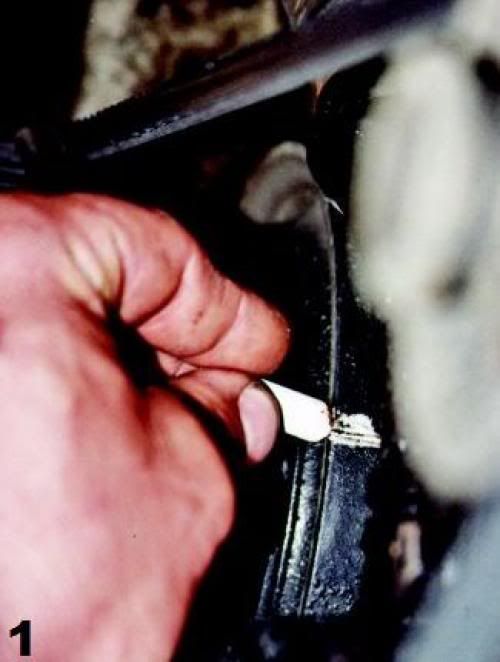
| Since the distributor is going to need to be removed from the engine, the timing marks will need to be cleaned and highlighted with either chalk or white paint. |
|
|
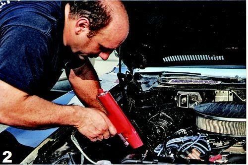
| If you are not familiar with the current distributor setting you should check the timing before removing the distributor. This way you will have a reference to go back to after you are done. Whenever using a timing light, always look directly at the timing plate and mark, not at an angle. If viewed at an angle, parallax error will occur. This means a false reading will be taken. The best example of parallax error is viewing the speedometer or gas gauge from the passenger seat. What is seen is not accurate. If you do not own a timing light and are going to purchase one, a dial-back or advance light is the best choice. This tool allows for easy plotting of the advance curve, though it is more expensive than a base light. |
|
|
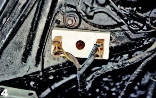
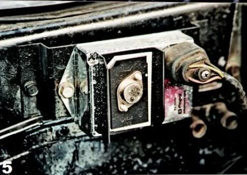
| All Mopars use a ballast resistor. Our subject car, owned by Kurt Mesmer, is a 1973 'Cuda with a 1967 383 and electronic ignition. The purpose of the ballast resistor is to reduce the running voltage to the points, or with electronic systems, to the control box. The engine cranks on full battery power; when the ignition key is released to the "Run" position, the current feeds through the resistor. Chrysler used two styles of ballast resistors; a single, or a double (as shown here). If the ballast is defective the engine will start, but stall as soon as the key is released to the "Run" position. |
|
|
| Procedure | Points Distributor | Electronic Distributor |
| If your car is using a Mopar electronic ignition system it will have a transistor box under the hood, usually on the firewall or inner fender. Mopar Performance (the old Direct Connection) sells a very nice kit for older breaker point Mopars to convert to true Chrysler electronic ignition. Many muscle cars have had this installation done over the years and is widely accepted as being correct and not considered a modification. |
|
|
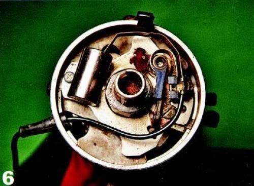
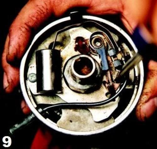
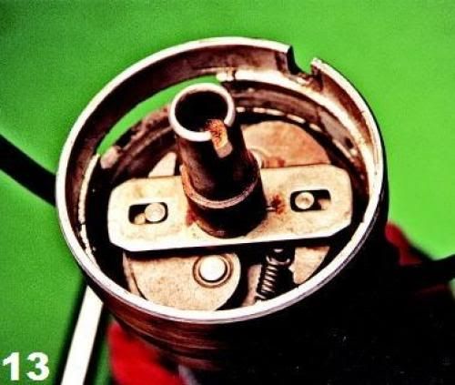
| With the distributor removed the components are in plain view. Our subject had an old set of Standard Ignition Products "Blue Streak" brand points. They are identified by the blue plastic on the arm and the auxiliary lubrication wick. The condenser attaches to the breaker plate with a screw. The wire that goes from the coil negative to the breakers is called a "pig tail" and is designed for a specific resistance. |
|
|
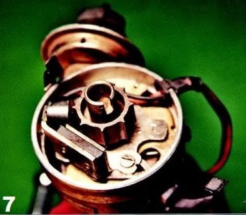
| The Mopar electronic distributor replaces the distributor cam, points, and condenser with a reluctor and a magnetic pick-up. |
|
|
| Procedure | Both Points and Electronic Distributor Types | |
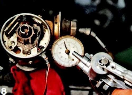
| Since the distributor is going to come completely apart, it is a good idea to check the vacuum advance canister for its integrity. A handheld vacuum pump will show if the diaphragm holds vacuum. If it is defective or hardly moves the breaker plate, now is the time to install a new one. The author suggests moving up to an adjustable vacuum advance canister that is offered by most performance ignition suppliers. |
|
|
| Procedure | Points Distributor | Electronic Distributor |
|
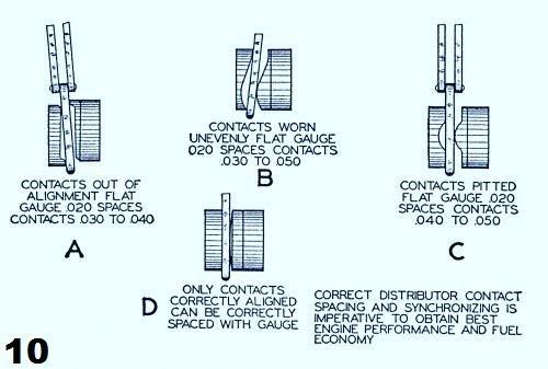
The first step is to remove the breaker points and condenser. After removal, examine the contacts to determine
the wear using the drawing in the next caption. Contact alignment is critical to proper performance. Were the breakers that you just removed aligned properly? |
|
|
| Procedure | Points Distributor | Electronic Distributor |
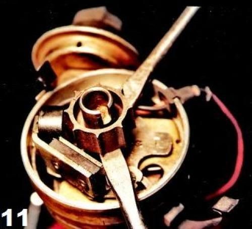
| On electronic designs, the reluctor needs to be pried off with two screw- drivers. There is a small roll pin that registers the reluctor in the proper place while holding it secure. DO NOT LOSE THIS PIN! |
|
|
| Procedure | Both Points and Electronic Distributor Types | |
| After removing the vacuum advance attaching screws, the canister can be slid out from the breaker plate. You may need to pry apart the breaker plate slightly to get the arm and locating point loose. |
|
|
| Procedure | Points Distributor | Electronic Distributor |
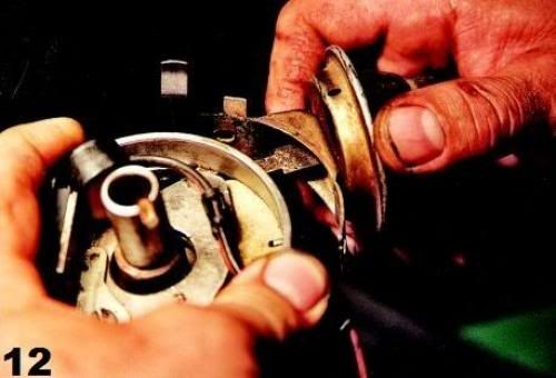
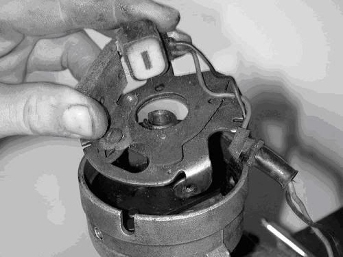
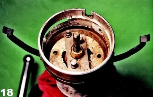
| Remove the 2 breaker/reluctor plate screws on the side of the distributor and remove the plate. With the breaker/reluctor plate removed this is what you will see on both the point and electronic distributors. The centrifugal weights reside under the stop mechanism which is attached to the shaft. |
|
|
| Procedure | Both Points and Electronic Distributor Types | |
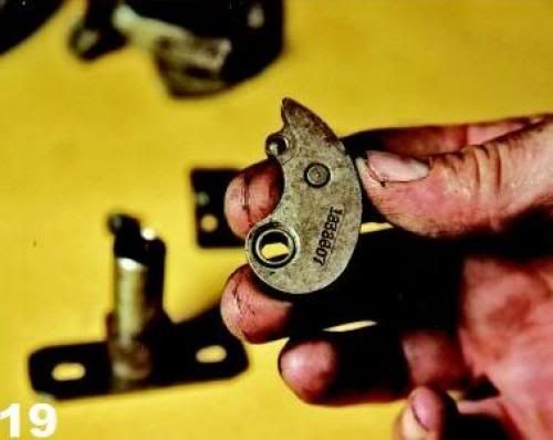
| Turn the breaker/reluctor plate over and slide the slotted spring steel clip to the large hole to separate the two parts of the plate. |

|
|
| Inspect and clean the breaker/reluctor plate halves. Check for any scoring. Often the incorrect point or condenser hold-down screw is used that is too long and scores or binds the plate. This results in the vacuum advance not working properly. Lubricate the slide bushings with a high-temperature grease. |

|
|
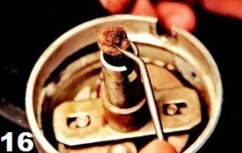
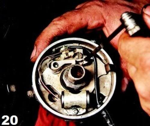
| To access the centrifugal weights the oil wick needs to be lifted out of place. |
|
|
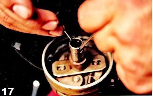
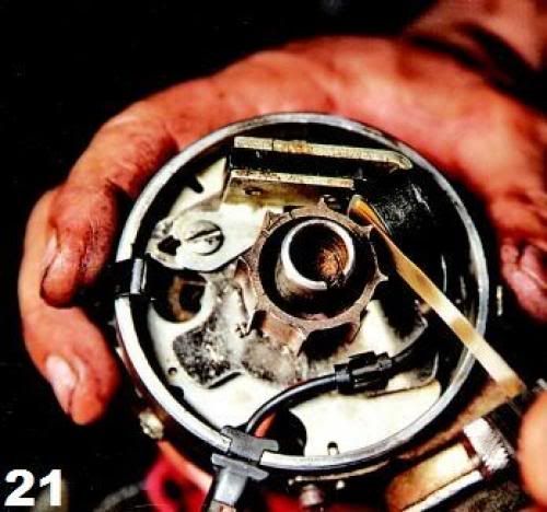
| A snap ring holds the stop to the distributor shaft. Usually it can be removed with either two very small screwdrivers or a combination of an awl and a screwdriver. This ring is frustrating to remove, so be patient. You will hardly ever get it out on the first try! Don't lose the removed ring. |
|
|
| With the weights removed, clean and inspect the shaft, bushing and pivot points. If any rust is present, use either a fine Scotch-Brite pad or light emery cloth to clean it off. Lubricate the pivot points with the same grease that was used on the breaker plate slides. Check the shaft for side-to-side freeplay. There should be no more than 0.008 inch of free play. If the play is excessive the distributor bushings in the case are worn and need to be rebuilt or a new casting purchased. |
|
|
| Inspect and clean the weights and springs. If you ever wanted to install a high performance advance kit, now is the time. Factory ignition parts are always of the highest quality and are worth the few extra dollars if you can still find them. |
|
|
| Procedure | Points Distributor | Electronic Distributor |
| Reverse the steps to assemble the distributor. With the new points installed, set the cam so that it is on the rubbing block. This will have the points fully open. Turn the shaft and watch the points open and close. Check the alignment and adjust if necessary. Place the rubbing block on the cam and using the proper specification, adjust the point gap using a feeler gauge. The gauge needs to be installed straight and the contacts should be rubbing slightly on each side when adjusted properly. Secure the screw when done. Turn the distributor and re-check the gap. |
|
|
| It's essential that the proper distributor cam lube is applied or the rubbing block will wear prematurely. Place a small amount on only one lobe. Then turn the distributor shaft quickly by hand to spread it to the other lobes. Carefully wipe any excess off the side of the rubbing block. Some brands of breaker points supply a small capsule of cam lube, or you can buy a tube from a better auto parts store, such as NAPA. The tube shown in the picture belongs to the author and is about 25 years old! |

|
|
| The Mopar electronic distributor has a reluctor gap. A special non-metallic feeler gauge (brass) is required. Set the gap between one lobe of the reluctor and the magnet. Most models used 0.008 inch, but reference a shop manual for the specification for your application. If the reluctor gap is set too wide, hard starting may occur due to a weak output signal. |
|
|
| Procedure | Both Points and Electronic Distributor Types | |
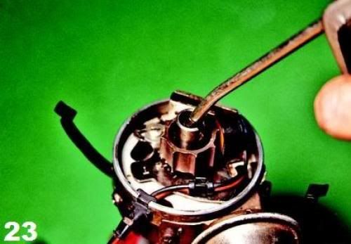
| The final and most important step is to moisten the center wick with engine oil. You want the wick wet, but not saturated with oil so that it flies out into the distributor cap. This oil lubricates the top shaft bushing and is essential for long service life. Do not forget to also check the distributor gear for wear. Install the distributor and set the ignition timing. Your Mopar will now run like never before. |
|
|
| « Maintaining a MOPAR Distributor | Ignition Specifications » |