|
|
GENERAL INFORMATION
Two sliding caliper disc brake assemblies are used as follows:
- Chrysler Single Piston Sliding Caliper Assembly:
These units are positioned with a intermediate adaptor attached to the steering knuckle
(Figs. 1 and 2).
- RM300 (73-74)
- M300 (74-78)
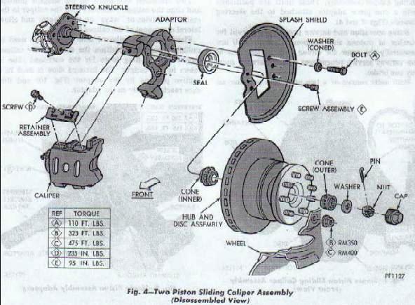
- Kelsey Hayes Dual Piston Sliding Caliper Assembly:
These units are positioned with a one piece adaptor attached to the steering knuckle
(Figs. 3 and 4).
- RM350 (73-74)
- RM400 (73-74)
- M300 (79 and Later)
- M400 (74 and Later)
- M500 (75 and Later)
- M600 (76 and Later)
|
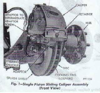
Figure 1
|

Figure 2
|
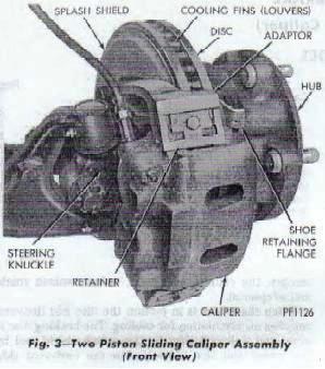
Figure 3
|
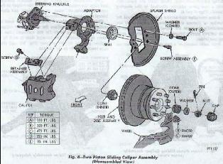
Figure 4
|
|
Brake operation and service procedures (except for number of pistons and component
attachment) are essentially the same for either unit. Illustrations of the various service
procedures will not always show any one brake. Both units consist of a two piece hub and
disc assembly, the caliper, shoes and linings, splash shield and adaptor(s).
When the wheel is in motion the disc {ins (louvers) supplies air circulation for cooling.
The braking disc is protected (inboard side) by the splash shield and by the wheel and tire
assembly on the outboard side (Fig. 5).
|
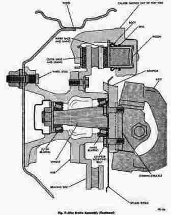
Figure 5
|
|
Two machined abutments on the adaptor position and align the caliper. Retainers hold the
caliper in the machined guides or "ways" on the adaptor and allow lateral movement of the
caliper (Fig. 7).
|
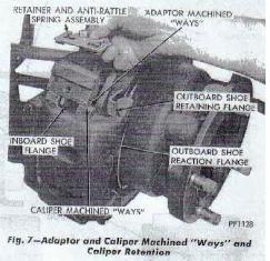
Figure 7
|
|
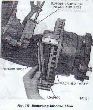
Flanges on the outboard shoe (Fig. 3) are used to radially locate and position the shoe on
the caliper fingers. All braking force for the outboard shoe is taken by the caliper. The
inboard shoe is held in a captive position by the adaptor (Fig. 10) and this shoe reacts
directly on the adaptor.
|
Figure 3
|
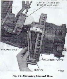
Figure 10
|
|
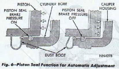
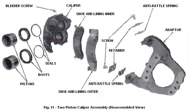
The caliper is a one piece casting with the inboard side containing the piston cylinder bore(s).
A square cut rubber piston seal is located in a machined groove in the cylinder bore(s) to
provide the hydraulic seal between piston(s) and cylinder walls.
A moulded rubber dust boot installed in a groove in the cylinder bore and piston keeps
contamination from the cylinder wall and piston. The boot has a wiping lip that prevents
contamination in the bore area (Fig. 6).
As the brake pedal is depressed, hydraulic pressure is applied against the piston(s). This
force pushes the inboard brake shoe and lining against the inboard braking surface of the
disc. As force increases against the disc from the inner lining, the caliper assembly moves
inboard, sliding on the machined adaptor "ways" (Fig. 7), thus providing a clamping force.
When the brake pressure is released, the piston seal (distorted by applied pressure) returns
to its normal position, pulling the piston back to released position (Fig. 6), creating a
slight running clearance between outer shoe and the disc.
Automatic adjustment is obtained by outward relocation of the piston as the inboard lining
wears and the inward movement of the caliper as the outboard lining wears, thus maintaining
correct adjustment at all times.
|
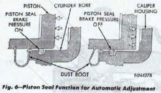
Figure 6
Figure 7
|
METERING VALVES
All sliding caliper disc brakes are equipped with combination brake warning/metering valve
(See "Hydraulic System Control Valves"). The metering unit
of the combination valve is to better match the front disc brakes with the rear drum brakes
on the vehicle. This results in improved braking and steering control.
Note:
1978 and later Dodge Motorhome Service Manuals refer to the combination brake warning/metering
valve as a combination brake warning/hold off valve.
SERVICE CHECKS
- The master cylinder fluid level should be checked at each lubrication period. Maintain
fluid level to within 1/4 inch of the top of the reservoir. Use only clean brake fluid
conforming to DOT 3.
- Linings should maintain light contact with the disc or have no more than .005 inch
clearance. How ever, if the vehicle was braked to a stop shortly before checking clearance,
it is normal for the brakes to drag. If the linings are more than .005 inch from the disc,
apply the brakes several times and recheck the clearance.
- "Knock-back" of the linings can be caused by the normal deflection of front suspension
components during a hard turn. In effect, the disc is tilted and knocks the linings and
pistons back. Excessive running clearance results and the driver will notice increased
pedal travel on the next brake application. Loose or worn suspension parts, especially
front wheel bearings, can increase the problem and cause the driver to pump the pedal
several times to get braking action. Check and adjust or replace loose, worn or broken
parts.
- Lining wear should be checked at least every 12,000 miles under normal operating
conditions. If operating conditions are severe, lining wear should be checked more
frequently.
- Lack of parallelism between the two faces of the disc, (variations in disc thickness)
may cause excessive pedal travel, a thrumming sound (front end vibration) or a pumping
(up-and-down movement) of the brake pedal when braking a moving vehicle. Disc thickness
must be checked if these symptoms are present.
- Disc lateral runout is "wobble" from side to side and can cause linings and pistons to
be "knocked back" causing increased pedal travel. lf the disc wobbles slightly when
rotated, even though the wheel bearings are in good condition and properly adjusted, the
wobble will usually not affect braking efiiciency. Disc lateral runout should be checked
whenever major service procedures are required on a sliding caliper disc brake system.
|
SERVICE DIAGNOSIS
|
BRAKE SHOES
Removal
- Raise vehicle on a hoist or jackstands.
- Remove front wheel covers, and wheel and tire assemblies.
- Remove caliper retainer and anti-rattle spring assemblies (Fig. 7).
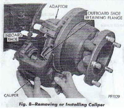
- Remove caliper from disc by slowly sliding caliper assembly out and away from disc
(Fig. 8).
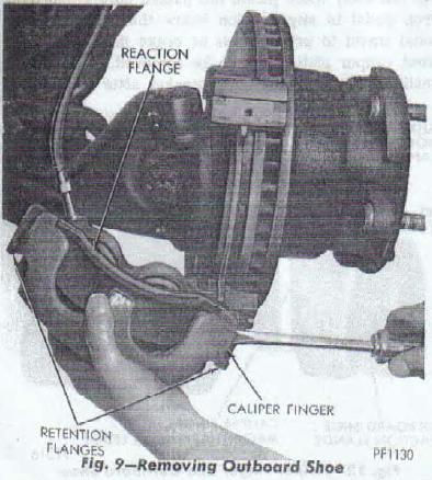
- Remove outboard shoe (flanges on outboard shoe will retain shoe to caliper) by prying
between shoe and caliper fingers (Fig. 9). Support caliper so as not to damage flexible
brake hose. Remove inboard brake shoe (Fig. 10).
|
Figure 07
|
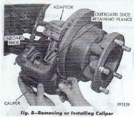
Figure 08
|
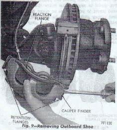
Figure 9
|
Figure 10
|
Inspection
Check for piston seal leaks (evident by brake fluid in and around boot area and inboard
lining) and for any ruptures of piston dust boot. If boot is damaged, or fluid is evident,
it will be necessary to disassemble caliper assembly and install a new seal, boot, (and
piston if damaged or corroded.) (Refer to "Disassembly" paragraph). Check the mating
surfaces of the abutments on the caliper and adaptor. If corroded or rusty, clean surfaces
with wire brush. Inspect braking surfaces of disc.
|
Reassembly
- Slowly and carefully push piston(s) back into bore until bottomed. Watch for possible
reservoir overflow.
- Slide new outboard shoe and lining assembly in recess of caliper.
CAUTION:
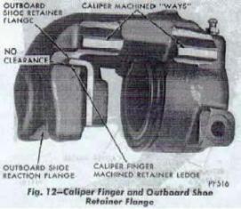
No free play between brake shoe flanges and caliper fingers (Fig. 12) should exist
(which might cause brake shoe rattle). If free play is evident by vertical shoe movement
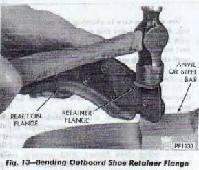
after installation, remove shoe from caliper and bend flanges (Fig. 13) to create slight
interference fit to eliminate all vertical free play when shoe is installed.
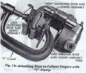
Install shoe after above moditication, if necessary, by snapping shoe into place with
fingers or with light "C" clamp, protect new lining from damage or contamination by using
old pads over new lining and across caliper fingers (Fig. 14).
- Position inboard shoe in position on adaptor with shoe "flanges" in the adapter "ways"
(Fig. 10).
- Slowly slide caliper assembly into position in adaptor and over disc. Align caliper on
machined ways of adaptor.
BE CAREFUL NOT TO PULL THE DUST BOOT FROM ITS GROOVE AS THE PISTON AND BOOT SLIDE OVER
THE INBOARD SHOE.
- Install anti-rattle spring and retainer assemblies and torque retaining screws to 235
inch-pounds.
- Pump brake pedal several times until a firm pedal has been obtained.
- Check and refill master cylinder reservoirs (if necessary) with DOT 3 brake fluid as
required. It should not be necessary to bleed the system after shoe and lining removal
and installation. However, if a firm pedal cannot be obtained bleed the brake system as
described in "Bleeding the Brake System" paragraph. It may have been necessary to remove
fluid to put in new linings as fluid is pushed back into the master cylinder.
- Install wheel and tire assemblies.
- Remove jack stands or lower hoist.
|

Figure 12
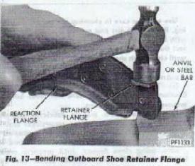
Figure 13
|
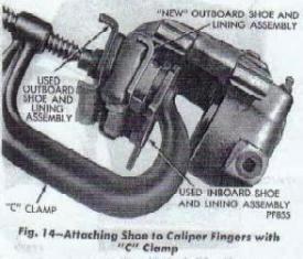
Figure 14
|
Figure 10
|
CALIPER
Removal
It will be necessary to remove the caliper to install a new piston seal and boot.
- Raise the vehicle on jackstands or hoist.
- Remove front wheel and tire assemblies.
- Disconnect flexible brake hose from caliper.
If pistons are to be removed from caliper leave brake hose connected to caliper.
See "Disassembly".
Plug brake tube to prevent loss of fluid, or prop brake pedal to any position below first
inch of travel. Disconnect hose from caliper.
- Remove retaining screw, retaining clip (and anti-rattle spring) that attach caliper to
adaptor (Fig. 7). Carefully slide caliper out and away from disc and adaptor (Fig. 8).
|
Figure 07
|
Figure 08
|
Disassembly
- Leave flexible brake lines attached to remove caliper piston(s), as follows:
- Single piston unit: support caliper assembly on axle and steering linkage on shop
towels to absorb any hydraulic fluid loss. Carefully depress brake pedal to
(hydraulically) push piston out of bore (brake pedal will fall away when piston has
passed bore opening). Prop pedal to any position below the first inch of pedal
travel to prevent loss of brake lluid. (If both front caliper pistons are to be
removed, disconnect llexible brake line at frame bracket after removing first
piston. Plug brake tube to remove piston from opposite side).
- Two piston units: support caliper assembly on axle and steering linkage. Place
2x4xl0 inch wood block spacer (Fig. 15) between caliper fingers and pistons (wood
spacer must be FULL TWO INCHES thick, this is allowable dimension piston can be
pushed out of bore and maintain hydraulic seal). Carefully depress brake pedal
until both pistons contact wood spacer. Pistons can now be removed. (Disconnect
flexible brake line at frame bracket and plug line to remove pistons from opposite
caliper). Prop brake pedal to any position below one inch of pedal travel to
prevent loss of hydraulic fluid.
CAUTION:
Under no condition should air pressure be used to remove piston(s) from bore(s)
personal iniury could result from such practice.
- Disconnect flexible brake hose from caliper.
- Mount caliper assembly in a vise equipped with protector jaws.
CAUTION:
Excessive vise pressure will cause bore distortion and binding of piston.
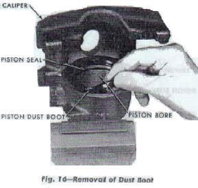
- Remove Dust boot (Fig. 16).
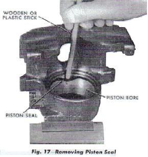
- Using a small, pointed wooden or plastic stick, work piston seal out of groove in piston
bore (Fig. 17). Discard old seal. Do not use a screwdriver or other metal tool for this
operation, because of possibility of scratching piston bore or burring edges of seal
groove.
|
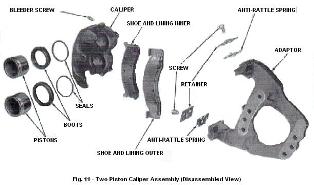
Figure 11
|
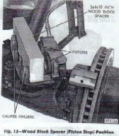
Figure 15
|
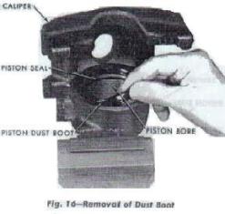
Figure 16
|
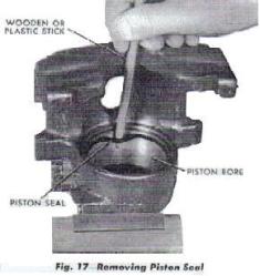
Figure 17
|
Cleaning and inspection
Clean all parts using alcohol or a suitable solvent and blow dry, using compressed air.
Blow out all drilled passages and bore. (Whenever a caliper has been disassembled, a new
boot and seal must be installed at reassembly). Inspect the piston bore for scoring or
pitting. Install a new piston if it is pitted, scored or the plating is severely worn. Bores
that show light scratches or corrosion, can usually be cleared with crocus cloth. However,
bores that have deep scratches or scoring should be honed (Fig. 18), using Tool C-4095,
providing the diameter of the bore is not increased more than .002 inch. If the bore does
not clean up within this specincation, a new caliper housing should be installed. Black
stains on the piston are caused by the piston seal and will do no harm.
When using Hone C-4095, coat the stones and bore with brake fluid. After honing the bore,
carefully clean the seal and boot grooves with stiff non-metallic rotary brush.
Use extreme care in cleaning the caliper after honing. Remove all dirt and grit by tlushing
the caliper with brake fluid; wipe dry with a clean, lintless cloth and then clean a second
time in the same manner or until clean cloth shows no signs of discoloration.
|
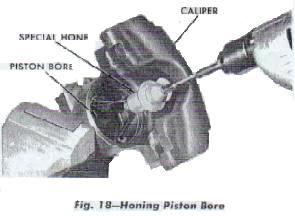
Figure 18
|
Assembly
- Clamp caliper in vise (with protector jaws).
Caution:
Excessive vise pressure will cause bore distortion and binding of piston.
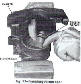
- Dip new piston seal in lubricant (supplied with kit) Ucon LB1145Y24 (or equivalent) and
install in groove in bore. Seal should be positioned at one area in groove and gently worked
around the groove, using clean fingers, until properly seated.
NEVER USE AN OLD PISTON SEAL. (Be sure seal is not twisted or rolled (Fig. 19).
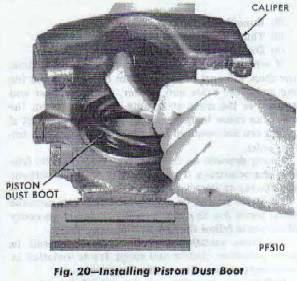
- Coat new piston boot with lubricant (as specified above) leaving a generous amount of
lubricant inside of boot. Install in caliper by working into outer groove, using fingers
only. (Boot will seem larger than diameter of groove, but will snap into place when properly
positioned in groove (Fig. 20). Using a forefinger, slide around inside of boot to be sure
it is seated, or correctly installed.
- Plug high pressure inlet to caliper and bleeder screw hole, (and opposite piston bore hole
on two piston units) then coat piston with a generous amount of lubricant (as specified
above). With fingers spreading boot, work piston into boot and press down on piston. (The
entrapped air below the piston will force the boot around the piston and into its groove as
the piston is depressed). Remove plug(s) then carefully push the piston down the bore until
bottomed.
Caution:
Force must be applied uniformly to avoid cocking. Reinstall high pressure inlet and remove
piston bore plug on two piston units and install second piston as described above. Before
installing caliper assembly on vehicle, inspect braking disc. Conditions described in
"Checking Braking Disc for Runout and Thickness" paragraph.
|
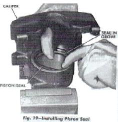
Figure 19
|
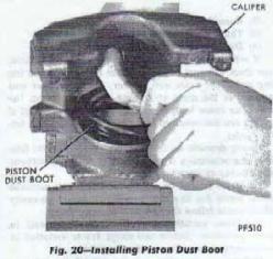
Figure 20
|
Installation
Examine lining for wear, damage or fluid contamination if its condition is found
satisfactory it may be reused. If not usable both front brakes must be relined with new
lining. If old lining is to be reused, be sure linings are installed in their original
position.
- Slide new outboard shoe and lining assembly in recess of caliper.
CAUTION:
No free play between brake shoe flanges and caliper fingers (Fig. 12) should exist (which
might cause brake shoe rattle). If free play is evident by vertical shoe movement after
installation, remove shoe from caliper and bend flanges (Fig. 13) to create slight
interference fit to eliminate all vertical free play when shoe is installed. Install shoe
after above modiiication, if necessary, by snapping shoe into place with fingers or with
light "C" clamp, protect new lining from damage or contamination by using old pads over
new lining and across caliper fingers (Fig. 14).
- Position inboard shoe in position on adaptor with shoe "flanges" in the adapter "ways"
(Fig. 10).
- Slowly slide caliper assembly into position in adaptor and over disc. Align caliper on
machined ways of adaptor.
BE CAREFUL NOT TO PULL THE DUST BOOT(S) FROM ITS GROOVE AS THE PISTON(S) AND BOOT(S)
SLIDE OVER THE INBOARD SHOE.
- Install anti-rattle spring and retainer assemblies and torque retaining screws to 235
inch-pounds.
- Attach flexible brake hose assembly to caliper using new copper gasket(s). Tighten to 25
footpounds.
- With bleeder screw open, allow caliper to "Gravity" fill with brake fluid, then close
bleeder screw. (Be sure all air bubbles have escaped; replenish brake fluid in master
cylinder. Bleed brakes as described under
"Bleeding Disc Brakes" paragraph).
- Pump brake pedal several times until a firm pedal has been obtained.
- After bleeding caliper, check for fluid tightness under maximum pedal pressures.
(Recheck master cylinder reservoir level).
- Install wheel and tire assembly. Tighten stud nuts as described in
"Front Axle" Group 2.
- Remove jackstands or lower hoist.
- Road test vehicle and make several stops to wear off any foreign material on the brakes
and to seat the linings. The vehicle may pull to one side or the other if this is not done.
|
Figure 12
Figure 10
|
Figure 14
|
Figure 13
|
BRAKING DISC
Checking for Runout and Thickness
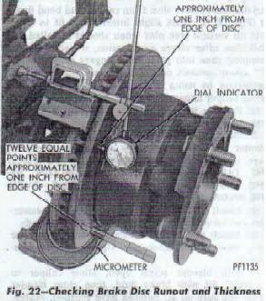
- Mount dial indicator C-3339 on steering arm with plunger contacting disc approximately
one (1) inch from edge of disc (Fig. 22).
- With wheel bearings adjusted to zero end play, check lateral runout. (Both sides of
disc). Runout should not exceed .004 inch. If runout is in excess of specification,
install a new disc and hub assembly or reface disc, being careful to remove as little as
possible from each side of disc. Remove equal amounts from each side of disc. Do not
reduce thickness below minimum thickness shown in refinishing section below. Be sure and
readjust wheel bearings after check.
- Thickness variation of disc should be made in conjunction with runout. Measure thickness
of disc at twelve (12) equal points with a micrometer at a radius approximately one (1)
inch from edge of disc. If thickness measurements vary by more than .0005 or .0008 inch,
(see chart below) disc should be removed and resurfaced
or a new disc and hub assembly installed (Fig. 22).
- Light scoring and/or wear is acceptable if heavy scoring or warping is evident, the disc
must be refinished or replaced (See Refinishing (
Refacing) Braking Disc). If cracks are evident the hub and disc assembly must be
replaced.
|

Figure 22
|
Remove Disc and Hub Assembly
- Raise vehicle on hoist or jackstands. Remove wheel cover and wheel and tire assembly.
- Remove caliper assembly, as described under "Removing Caliper" paragraph, (but do not
disconnect brake line). Suspend caliper from wire hook or loop to avoid strain on
flexible hose.
- Remove grease cap, cotter pin, nut lock, nut, thrust washer and outer wheel bearing.
- Pull disc and hub off wheel spindle.
Inspection
Before refinishing or refacing a breaking disc, the disc should be checked and inspected for
the following conditions:
- Scoring, rust, impregnation of lining material and worn ridges.
- Runout or wobble.
- Thickness variation (Parallelism).
- Dishing or distortion (Flatness).
If vehicle has not been driven for a period of time, the discs will rust in the area not
covered by the lining and cause noise and chatter, excessive wear and scoring of the discs
and lining. Wear ridges on the discs can cause temporary improper lining contact if ridges
are not removed before installation of new lining (pads).
Lining deposits on the disc, may cause erratic friction characteristics if new lining is
installed without resurfacing or cleaning the disc.
Excessive runout or wobble in a disc can increase pedal travel due to piston knockback due
to necessity of caliper to follow the disc wobble.
Thickness variation in a disc can also result in pedal pulsation, chatter and surge due to
variation in brake output when disc section is uneven.
Dishing or distortion can be caused by extreme heat and abuse of the brakes.
Resurfacing Braking Disc
This operation can be used when the disc surface is rusty or has lining deposits. A sanding
disc attachment will remove surface contamination without removing much material. It will
generally follow variations in thickness which are in the disc.
|
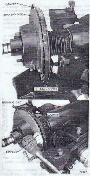
Refacing Braking Disc
If scoring is deep, runout or thickness variation is beyond limits, or other distortion is
apparent, the disc should be refaced on a brake lathe equipped for disc machining (Fig. 23).
After machining a disc, a grinder may be used to remove tool marks.
A new disc and hub assembly should be installed if the old one cannot be refaced to bring it
within specifications without removing an excessive amount of material. Do not remove more
than .030 inch per disc. Brake operation may be affected if an excess of material is removed.
Both sides of the braking surface should be machined or ground an equal amount when servicing
since small variations in resurfacing machines may cause the newly finished surface to be
out of parallel with the opposite unfinished side resulting in a thickness variation beyond
acceptable Disc brakes are very sensitive to thickness variation.
Caution:
When refacing a braking disc, the manufacturers of the refacing equipment instructions
should be followed closely, and the correct brake disc mounting adaptors must be used to
obtain the required specifications.
|
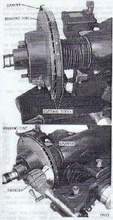
Figure 23
|
|
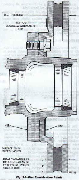
The following chart and (Fig. 24) shows the location and tolerances of required
specifications when servicing the braking disc:
| Model |
Thickness |
Thickness
Variation |
Runout |
Micro
Finish |
| M300 (RM300) |
1.170-1.190 |
.0005 |
.004 |
15-80 |
M400 (RM350)
M500 (RM400)
M600 |
1.520-1.550 |
.0008 |
.005 |
15-80 |
|
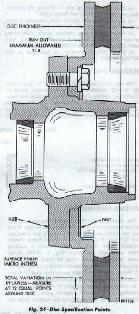
Figure 24
|
Install Disc and Hub Assembly
- Slide brake disc and hub assembly on spindle.
- Install outer bearing, thrust washer and nut.
- Tighten wheel bearing adjusting nut to 240-300 inch-pounds while rotating disc and hub.
Recheck disc runout as described previously.
- Back off adjusting nut to release all preload, then retighten adjusting nut finger tight.
- Position lock nut on nut with one pair of slots in line with cotter pin hole. Install
cotter pin.
- Clean grease cap, coating inside with wheel grease (do not fill cap) and install cap.
Clean both sides of braking disc with alcohol or suitable solvent.
- Install caliper assembly, as described in "Installing Caliper" paragraph.
BLEEDING DISC BRAKE
The disc brake hydraulic system can be bled manually or with pressure bleeding equipment.
Refer to "Hydraulic System Control Valves" section for lockout during bleeding procedure.
On disc brake equipped vehicles, the brake pedal will require more pumping, and frequent
checking of the fluid level in the master cylinder during the bleeding operation.
Never use brake fluid that has been drained from the hydraulic system, when bleeding the
brakes.
On vehicles equipped with disc brakes, be sure that the disc brake piston is returned to a
normal position and that the shoe and lining assemblies are properly seated.
Before driving the vehicle, check the operation of the brakes to be sure that a firm pedal
has been obtained.
- Raise vehicle using a hoist or jackstands.
- Bleed brakes in usual manner, starting with right rear, then proceeding to left rear,
right front and left front in order.
After bleeding the brakes, proceed as follows;
- Remove jackstands or lower hoist.
- Test drive vehicle to be sure brakes are operating correctly and that pedal is solid.
|
|