Dave's Place
Wagner Dual System Master Cylinder
GENERAL INFORMATIONThe dual master cylinder used with the split hydraulic service brake system on M-375 chassis produced after February 1971 (Fig. 2) is a split-ratio, dual reservoir device with a 1.75 inch bore. The front piston displaces 40 percent and the rear piston displaces 60 per cent. The rear outlet is connected to a frame mounted Bendix Hydrovc unit which is in turn connected to the wheel cylinder on each of the front wheel brake assemblies and to one wheel cylinder on each of the rear wheel brake assemblies. The front outlet is connected to a second frame-mounted Bendix Hydrovac unit which is connected to the other wheel cylinder in each of the rear wheel brake assemblies. If these components are disconnected for any reason, be careful that the split hydraulic brake system on the M-375 chassis is reconnected exactly as it was disconnected (Fig. 1, also see "Brake Hose and Tubing" this Group). |
|
|
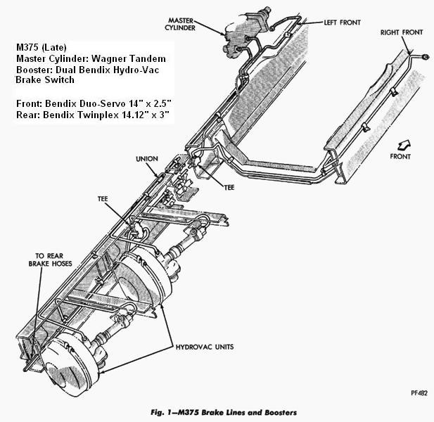 Figure 1 |
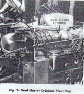 Figure 2 |
|
SERVICE PROCEDURESDisassembly
|
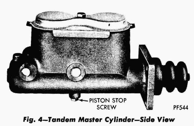 Figure 4 |
|
 Figure 3 LEGEND FOR FIGURE 3 | ||
|
1. Rear Piston Seal Cup
2. Rear Piston 3. Cover Seal 4. Reservoir Cover 5. Gasket 6. Cover Bolt 7. Intake Port 8. By Pass Port |
9. Reservoir Housing
10. Tube Seat 11. Front Piston Return Spring 12. Front Piston Pressure Cup 13. Floating Front Piston 14. Front Piston Seal Cup 15. Gasket |
16. Stop Bolt
17. Rear Return Spring Retainer 18. Rear Return Spring 19. Rear Piston Stop Pin 20. Rear Piston Pressure Cup 21. Stop Plate 22. Retainer Ring |
Cleaning and InspectionClean all parts in clean brake fluid or alcohol. If the reservoir housing is clegreased,
finish clean to remove all trace of other solvents. Inspect the cylinder bore for scratches
or corrosion. Minor blemishes can be removed with crocus cloth. Check by-pass ports in both reservoirs to make sure that they are open and free of burrs. Probe parts with soft copper wire 0.020" in diameter or smaller. Do not use steel wire to check ports. This may scratch master cylinder or cause burrs in ports. Remove and discard all rubber parts. All rubber parts are included in the repair kit which is available from regular service parts sources. |
||
Assembly (Fig. 5)
|
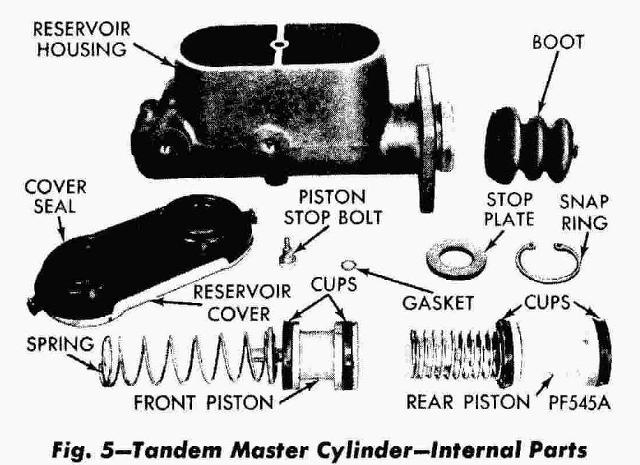 Figure 5 |
|