The Bendix Duo-Servo is a basic duo-servo single-anchor brake of advanced and improved design.
Front and rear brake assemblies are basically the same, except that rear brakes on M-300 Motor
Home chassis produced after April 1, 1972 include a parking brake lever and cam plate (Fig. 1).
M-300 Motor Home chassis produced prior to April 1, 1972 are equipped with transmission-mounted
parking brakes. All Bendix Duo-Servo brake assemblies used in Motor Home chassis applications
are self-adjusting.
Bendix Duo-Servo brakes are used as follows:
Front: M300 and M375 models
Rear: M300, RM300 and RM350 models
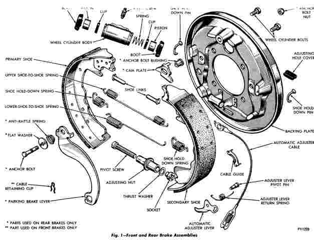
Front Wheel Duo-Servo brake
Figure 1
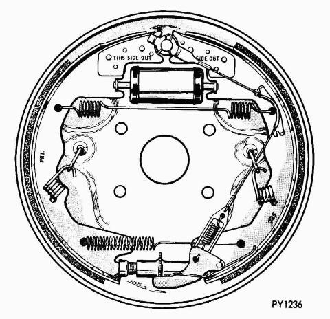
Brake shoes are marked "Pri" (primary) and "Sec" (secondary) and also "This Side Out" for easy
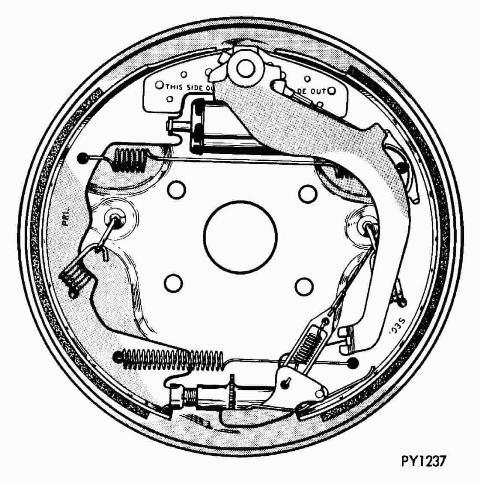
identification and installation. Typical front and rear assemblies are shown in Figs. 2 and 3.
Figure 2 - Front Brake Assembly
Figure 3 - Rear Brake Assembly
A two-piston wheel cylinder is mounted in an indentation on the brake support plate. The wheel
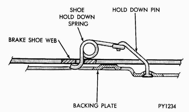
cylinder must be removed from the support plate for service. Each brake shoe is held against
the support plate by a coil spring, hold-down pin combination (Fig. 4).
Figure 4 - Coil Spring Hold down pin Combination
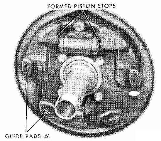
Each support plate has six guide pads, three for each shoe (Fig. 5). The shoe webs ride against
these pads.
Figure 5 - Support Plate and Guide Pads
SERVICE PROCEDURES
Brake Drum Replacement YouTube Video
This Youtube video is for a D/W350 pickup however, the Motorhome chassis brakes are the same
BRAKE DRUM REMOVAL
Front
Raise vehicle on hoist or jacks and install jackstands for safety.
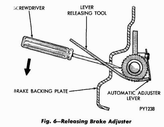
lf there is interference between brake shoes and drum, remove hole cover and using a
screwdriver and light piece of metal, release brake shoes (Fig. 6).
Rear
Raise vehicle on hoist or jacks and install jack stands for safety.
Remove wheel and tire assembly.
Remove axle shaft nuts, washers and cones. Rap axle shaft sharply in center to release
cones if they do not readily release. Remove axle shaft.
Using Tool DD-1245 remove outer hub nut. Straighten lock washer, remove it, inner nut and
bearing. Carefully remove drum. CAUTION:
lf there is interference between brake shoes and drum, remove hole cover and using a
screwdriver and light piece of metal, release brake shoes (Fig. 6).
Figure 6 - Release Brake Lever
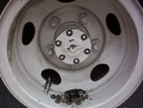
Axle Nuts, Washers, and Cones
Removing Axle
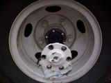
Axle Removed, Drum still On
DRUM REFACING
Measure the drum runout with an accurate gauge. Drum runout should not exceed .006 inch out
of round. If the drum runout is in excess of .006 inch, (total indicator run-out) the drum
should be refaced. Remove only as much material as is necessary to clean up the drum. Do
not reface more than .060 inch over the standard drum diameter.
BRAKE SHOE REMOVAL
Front
Unhook adjusting lever return spring from the lever (Fig. 1).
Remove lever and return spring from lever pivot pin. Unhook adjuster lever from adjuster
cable assembly.
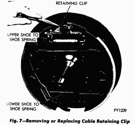
Remove cable retaining clip (Fig. 7) and remove cable.
Using brake spring pliers (Tool C-312) (Fig. 8) unhook upper shoe-to-shoe spring. Unhook and
remove shoe hold down springs (Fig. 9).
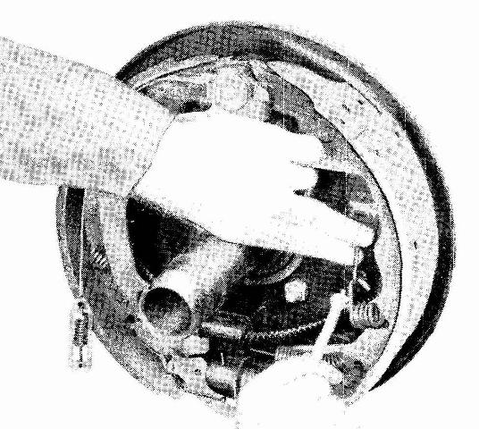
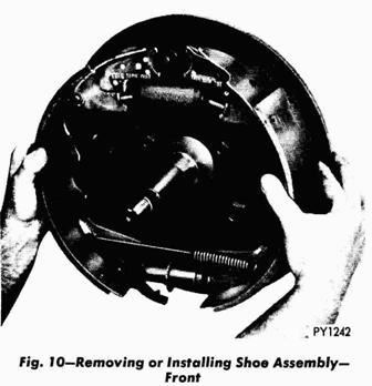
Remove shoe with lower shoe-to-shoe spring and star wheel as an assembly (Fig. 10).
Front Wheel Duo-Servo brake
Figure 7 - Removing or Replacing Cable Retaining Clip
Figure 9 - Removing or Installing Shoe Hold Down Springs (Front)
Figure 8 - Removing or Installing Upper Shoe-to-Shoe Spring (Front)
Figure 10 - Removing or Installing Shoe Assembly (Front)
Rear
Unhook adjusting lever return spring from the lever (Fig. 1).
Remove lever and return spring from lever pivot pin. Unhook adjuster lever from adzuster
cable assembly.
Using brake spring pliers (Tool C-312) (Fig. 11) unhook upper shoe-toshoe spring. Unhook and
remove shoe hold down springs (Fig. 12).
Disconnect parking brake cable from parking brake lever.
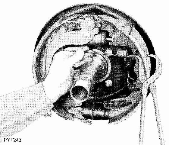
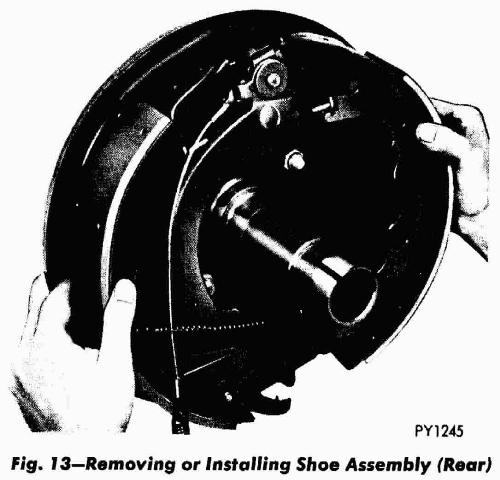
Remove shoes with lower shoe-to-shoe spring and starwheel as an assembly (Fig. 13).
Figure 11 - Removing or Installing Upper Shoe-to-Shoe Spring (Rear)
Figure 12 - Removing or Installing Shoe Hold Down Springs (Rear)
Figure 13 - Removing or Installing Shoe Assembly (Rear)
CLEANING AND INSPECTION
Wipe or brush clean (dry) the metal portions of the brake shoes. Examine the lining contact pattern
to determine if the shoes are bent. The lining should show contact across the entire width, extending
from heel to toe. Shoes showing contact only on one side should be replaced. Shoes having sufficient
lining but lack of contact at toe and heel should be measured for proper grind.
Clean the support, using a suitable solvent, then inspect for burrs. Remove if necessary. Clean the
threads of the adjusting screws, then inspect for pulled or stripped threads.
BRAKE SHOE INSTALLATION
Front
Pivot screw and adjusting nut have left hand threads on left brake assemblies (brakes on left
side of the vehicle) and right hand threads on right hand assemblies (brakes on right side of
the vehicle).
Lubricate and assemble starwheel assembly. Lubricate guide pads on support plates (Fig. 5)
with MOPAR Parts Multi-Purpose Grease, Part Number 2932524 or equivalent.
Assemble starwheel, lower shoeto-shoe spring and primary and secondary shoe and position on
support plate (Fig. 10).
Install and hook hold down springs (Fig. 9). Using brake spring pliers (Tool C-312) replace
upper shoe-to-shoe spring (Fig. 8).
Install cable and retaining clip (Fig. 7).
Position adjuster lever return spring on pivot (green springs on left brakes and red springs
on right).
Install adjuster lever. Route adjuster cable and connect to adjuster.
Front Wheel Duo-Servo brake
Figure 5 - Support Plate and Guide Pads
Figure 10 - Removing or Installing Shoe Assembly (Front)
Figure 8 - Removing or Installing Upper Shoe-to-Shoe Spring (Front)
Figure 9 - Removing or Installing Shoe Hold Down Springs (Front)
Figure 7 - Removing or Replacing Cable Retaining Clip
Rear
Pivot screw and adjusting nut have left hand threads on left brake assemblies (brakes on left side
of the vehicle) and right hand threads on right hand assemblies (brakes on right side of the vehicle).
Lubricate and assemble starwheel assembly. Lubricate guide pads on support plates (Fig. 3)
with MOPAR Parts Multi-Purpose Grease, Part Number 2932524 or equivalent.
Assemble starwheel, lower shoe-to-shoe spring and primary and secondary shoe and position
on support plate (Fig. 13).
Connect parking brake cable to parking brake lever.
Install and hook hold down springs (Fig. 12). Using brake spring pliers (Tool C-312) replace
upper shoe-to-shoe spring (Fig. 11).
Position adjuster lever return spring on pivot green springs on left brakes and red springs
on right).
Install adjuster lever. Route adjuster cable and connect to adjuster.
Figure 13 - Removing or Installing Shoe Assembly (Rear)
Figure 12 - Removing or Installing Shoe Hold Down Springs (Rear)
Figure 11 - Removing or Installing Upper Shoe-to-Shoe Spring (Rear)
BRAKE DRUM INSTALLATION
Front
Position drum on spindle.
Install bearing, washer and nut. Adjust bearing (See Group 2) of manual.
Install nut lock, cotter key and dust cover.
Install wheel and tire assembly.
Remove jack stands and lower vehicle.
Rear
Position drum on axle housing.
Install bearing and inner nut. Adjust bearing (See Group 3) of manual.
Install locking washer and outer nut. Bend locking washer to secure. Place new gasket on
hub and install axle shaft, cones lock washers and nuts.