GENERAL INFORMATION
Hydro-Vac units are used in pairs on RM350 and RM400 models (Figs. 1 and 2) and M375 models when equipped with tandem master cylinder (Wagner) and split service brake hydraulic system. The booster units are single diaphragm vacuum operated and are made up of three functional components:
- power section
- hydraulic slave cylinder
- vacuum control valve.
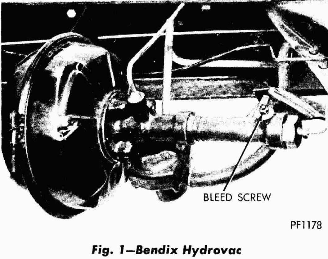
Figure 1
Hydro-Vac booster on Dodge Motorhome
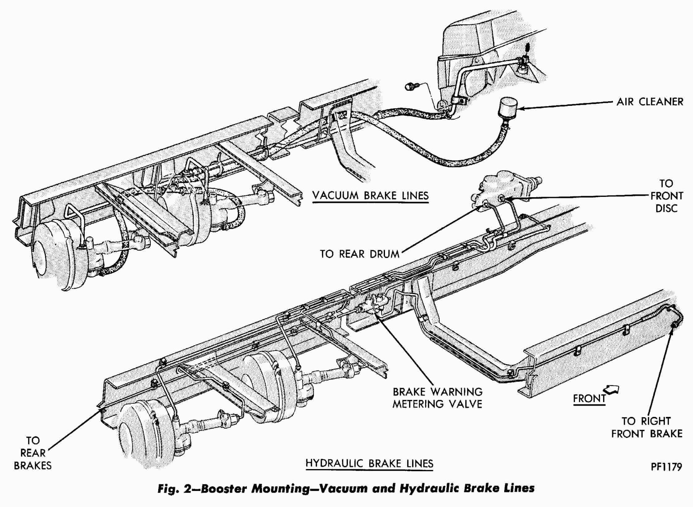
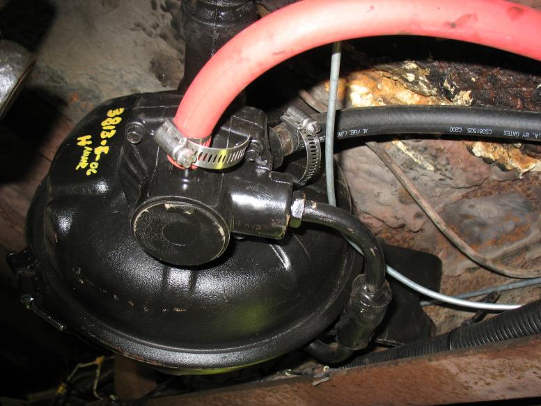
Figure 2
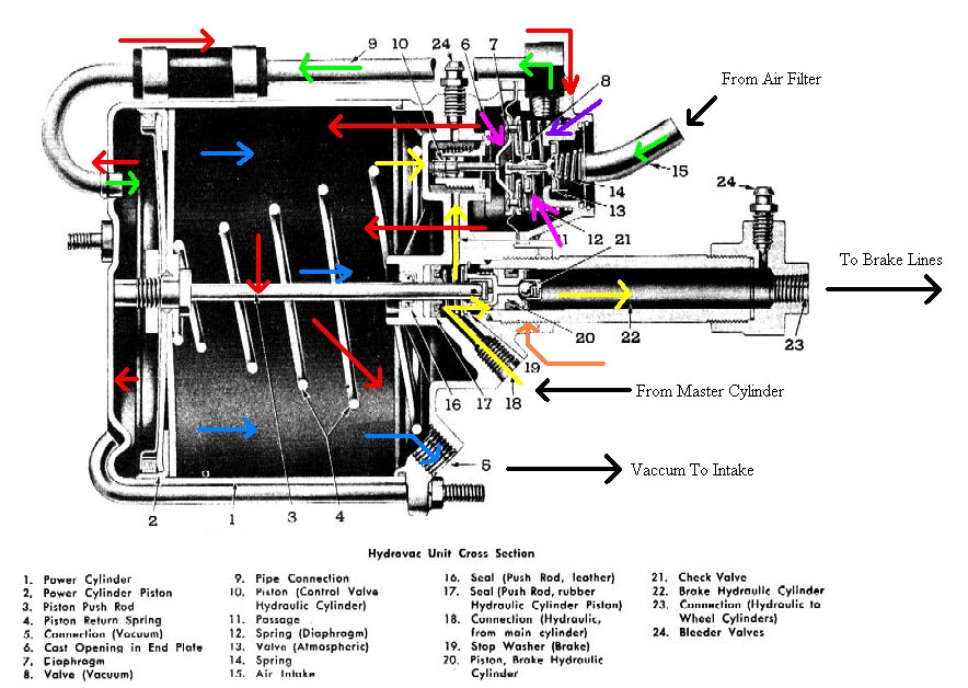
Operation
Information courtesy of www.stovebolt.comNote
The operational descriptions are for different styles of Hydro-Vac boosters however, the
principles are the same for all Hydro-Vac boosters
As pressure is applied to the brakes, fluid is passed into the Hydro-Vac (yellow). It by-passes the hydraulic brake piston (# 20, thanks to the check ball), and pressure goes through the lines to the wheel cylinders. At the same time it also passes through a pathway in the unit and applies pressure to (# 10) the control valve hydraulic piston. As more pressure is applied to the brakes, the control valve piston pushes up on the metal rod on the rubber diaphragm (# 7). The metal portion of the diaphragm has an air pathway through the center which allows air flow circulation throughout the unit (through the tube (# 9) to the rear of the power cylinder piston). The atmospheric / vacuum valve (# 8 and # 13) is a two part valve located above the diaphragm. It blocks air coming into the Hydrovac due to the spring (# 14) under the intake tube. Brake pressure changes cause the vacuum valve to seat on the rubber diaphragm (shown in pink), sealing the air passage through it and effectively blocking any air coming into the power cylinder (# 1) between the ports (# 6) located in the end plate of the unit and the connecting tube (# 9).
Bendix Hydro-Vac booster
As pressure builds and the diaphragm is pushed even further forward, the atmospheric valve portion opens (shown in purple) allowing air to enter the power cylinder (air path shown in green) and letting the vacuum from the engine pull the power cylinder piston (# 2) forward which pushes the hydraulic brake piston (# 20) into the hydraulic cylinder (# 22). The check ball has pressure from the brake lines pushing back against it now (orange) and seats inside the piston allowing no brake fluid to pass by it back into the master cylinder. Therefore, the piston pushes more brake fluid forward in the lines and braking power increases.
The whole system uses brake pressure to overpower the springs and engage / disengage the control body valves. The reason this system works the way it does is that the vacuum created by the engine is able to travel throughout the Hydrovac unit (shown in red). Therefore with vacuum in front of and behind the power piston, there is equal pressure on both sides. So until the valves close off that circulation and opens the air intake, the power cylinder piston won't move. Closing one valve stops that circulation throughout the unit. Opening the intake allows the cylinder to pull air from behind so the vacuum can pull the power cylinder piston forward.
YouTube - Old Army Hydro-Vac Training Video
Service Procedures
TESTING HYDROVAC UNIT ON MOTOR HOME
With Gauges
- Install a tee in the vacuum supply line and connect a vacuum gauge to the tee.
- Connect a 0-2000 psi. hydraulic gauge to the bleed screw port in the output end of the slave cylinder with a bleed screw adapter, to a tee in the hydraulic line or to a bleed screw port in one of the wheel cylinders with a bleed screw adapter. Connection to the most convenient of these points is recommended.
- Connect a 0-600 psi. hydraulic gauge in the input side of the power unit by installing a tee in the input hydraulic line. Re-bleed the system if necessary to eliminate any air in the hydraulic system.
- Apply the brakes (without starting the engine) and check for hydraulic leaks and agreement between the hydraulic gauges. lf the pedal "falls away" under constant pedal pressure or if the gauges indicate a drop in hydraulic pressure correct any leaks that may be found. If no external leaks are in evidence and leaks are indicated by the pedal or gauges, an internal leak is present which must be corrected before further tests may be run.
- With the brakes released and the engine running, the vacuum gauge should show a manifold vacuum of approximately 20 inches 1 3 inches.
- Run the engine one minute with the brakes released and note any drop in the vacuum gauge reading. If the rate of vacuum loss exceeds 2 inches of Mercury in 15 seconds, excessive air is leaking into the system. Shut the engine off.
- Restart the engine with the brake pedal depressed. If the vacuum system is operating satisfactorily, the brake pedal should move toward the floor.
- Again depress the brake pedal and observe the gauge readings. The supply vacuum gauge should continue to read manifold vacuum except for a slight fluctuation. The input and output hydraulic gauges should increase smoothly as pedal pressure is increased.
- Release the brake pedal and note the reading on the output hydraulic gauge. The pressure must decrease smoothly to zero as the pedal is released.
- With the engine running, depress the brake pedal sufficiently to create approximately 1000 psi. hydraulic output pressure. Hold the 1000 psi. pressure for about one minute, increasing pedal pressure if necessary. lf the pedal requires increased force to maintain the 1000 psi. pressure or if the pedal moves slowly to the floor while maintaining the 1000 psi. pressure, a high pressure leak is indicated. Check for leaks in the rest of the brake system (hoses, fittings, wheel cylinders, etc.) before removing the Hydrovac for repair or replacement.
- If the basic hydraulic brake system, the vacuum power system and the Hydrovac are found to be in satisfactory operating condition, the vehicle can be returned to service. Remove all gauges and test fittings and restore the original brake system connections. Re-bleed the entire hydraulic system, remembering that air has probably entered the system while removing the test fittings. This may require a longer bleeding time to make sure that all air has been removed from the wheel cylinders.
Without Gauges
The procedures below are guides for checking a vacuum hydraulic power brake system to determine whether or not the power unit and its related systems are operating satisfactorily.
Many brake problems are caused by trouble in the wheel brake assemblies, master cylinder or in the related vacuum and hydraulic systems. Because of this the Hydrovac unit should not be removed and replaced unless tests show that it is definitely contributing to the problem. An accurate test of the Hydrovac cannot be made unless irregularities in other parts of the brake system have been corrected prior to testing the Hydrovac.
Failure of brakes to function properly at below freezing temperatures may be caused by moisture in various parts of the system. In this case, all sections must be inspected, the moisture removed and the source of moisture entrance located and corrected.
Vacuum Power Check
- Apply the brake pedal with the vehicle ignition off to remove all vacuum from the system.
- Depress the brake pedal, hold foot pressure on it and then start the engine.
- If the vacuum system is operating properly, the pedal will move downward.
- If no action is felt, the vacuum system is not operating properly. Inspect the system for a disconnected or restricted vacuum supply line. Remove the vehicle from service until the trouble has been located and corrected.
BENCH OVERHAUL
If tests indicate that the Hydrovac unit is the source of the brake problem, the unit must be removed from the Motor Home and completely reconditioned or replaced. Follow the procedures outlined below for bench overhaul.
Before removing the Hydrovac unit from the vehicle:
- Disconnect all vacuum and hydraulic lines and tag them to facilitate reassembly.
- Plug all ports and thoroughly clean the outside of the unit.
- Wire brush all dirt and mud off the outside of the unit. Remove all oil, grease and foreign matter.
- Disconnect Hydrovac mounting bracket from longitudinal frame member and remove unit.
DISASSEMBLY (Fig. 3)
Use extreme care in handling hydraulic system parts to prevent getting mineral oil or grease on them.DO NOT HANDLE RUBBER CUPS OR SEALS WITH GREASY HANDS!
When reconditioning a Hydrovac unit always use the approved Bendix repair kit.
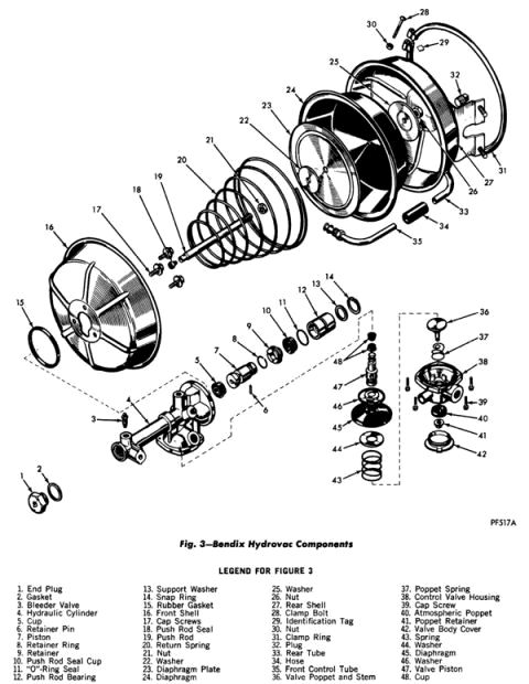
Figure 3
Removal of Control Tube, Clamp Band, Rear Shell and Diaphragm (Fig. 4)
- Scribe a mating mark across front and rear shells.
- Clamp hydraulic cylinder in bench vise.
- Slide vacuum hose on control tube toward hydraulic cylinder end.
- Remove control tube with hose from control valve housing.
- Remove nut and clamp bolt, identification tag, clamp ring and rear shell.
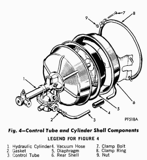
Figure 4
Removal of Diaphragm, Spring, Front Shell and Gasket (Fig. 5)
- Turn outer rim of diaphragm back to expose hex nut on push rod.
- Hold push rod with open end wrench and loosen nut.
- Caution: Maintain pressure on spring during this operation to prevent
return spring from flying.
Bear down heavily on diaphragm and plate to offset diaphragm return spring load and remove nut, washer, diaphragm, diaphragm plate, washer and return spring. - Remove three cap screws and lift front shell from flange of hydraulic cylinder.
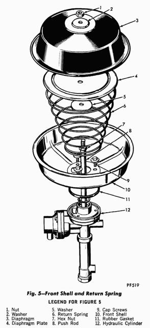
Figure 5
Removal of Control Valve, Spring, Diaphragm and Valve Piston (Fig. 6)
- Scribe mating mark across flanges of control valve and hydraulic cylinder housing.
- Remove four cap screws and lift off control valve housing and spring.
- Remove washer, diaphragm, washer, piston and two cups.

Figure 6
Control Valve Disassembly (Fig. 7)
- Remove cover from control valve housing.
- Pry off poppet retainer, lift off atmospheric poppet.
- Remove valve poppet and stem and poppet spring from valve housing.
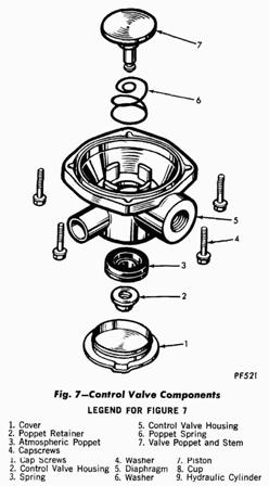
Figure 7
Removal of Push Rod, Bearing and Piston Assembly (Fig. 8)
- Push hydraulic push rod in to the end of its stroke and remove snap ring and support washer.
- Pull push rod and piston out.
- Remove "O" ring seal, push rod bearing, push rod seal cup and retainer from push rod.
- Remove end plug, gasket and bleeder screws from cylinder housing.
- Remove snap ring and residual pressure check valve parts.
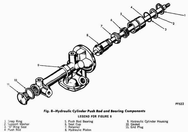
Figure 8
Removal of Piston From Push Rod und Cup From Piston (Fig. 9)
- Slide retainer ring out of groove in piston.
- Separate piston from push rod by removing retainer pin.
- Remove cup from piston with ice-pick or thin-bladed screwdriver.
- If push rod seal in end of push rod must be replaced, grip seal with pliers, pull from end of push rod and discard.
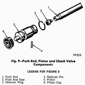
Figure 9
CLEANING AND INSPECTION
Clean all metal parts thoroughly. Alcohol may be used for cleaning component parts as long as parts are completely air-dried and coated with brake fluid before installation.
DO NOT USE ALCOHOL FOR FLUSHING SYSTEM OR CLEANING ASSEMBLIES WHERE ALCOHOL COULD BE TRAPPED AND SUBSEQUENTLY CONTAMINATE BRAKE FLUID.
Inspect all parts not included in the repair kit for excessive wear and damage. Replace all worn or damaged parts. Inspect control valve body atmospheric valve seat. If damaged, replace housing. Always use a factory-approved repair kit when reconditioning a Hydrovac unit.
ASSEMBLY
Hydraulic Piston and Push Rod (Fig's 8 and 9)
- To install a new seal in push rod, place new seal on clean wooden block with the rubber� faced side of the seal down.
- Position push rod directly above seal, vertical and with the threaded end up. Strike end of push rod with rawhide hammer to seat seal in end of push rod.
- Dip cup in brake fluid and install on piston with lip away from push rod.
- Insert seal end of push rod in piston.
- Push retainer pin through holes in piston and push rod and secure with retainer ring. Be sure ring is seated in piston groove.
- Install a new residual check valve in end plug with spring, washer and snap ring (Fig. 9).
Figure 9
Push Rod Bearing and Piston Assembly (Fig. 8)
- Install seal retainer, push rod seal cup and push rod bearing over threaded end of push rod.
- Install "O" ring seal in outer groove of bearing and guide piston and push rod assembly into bore of hydraulic cylinder.
- Press bearing into housing and install support washer and snap ring in snap ring groove of hydraulic cylinder.
- Place new gasket on end plug and install end plug in hydraulic cylinder. Tighten end plug to 50-85 foot-pounds.
- Replace bleeder screw.
Figure 8
Control Valve (Fig. 7)
- Install poppet return spring, valve poppet and stem and atmospheric poppet in valve housing.
- Snap poppet retainer over end of valve stem.
- Install cover.
Figure 7
Valve Piston, Diaphragm, Spring and Valve Assembly (Fig. 6)
- Dip cups into brake fluid and install on piston back to back.
- Install washer and diaphragm. Seat diaphragm in piston groove.
- Insert valve piston in hydraulic cylinder bore and install spring retainer, spring and valve housing.
- Align housing to mating scribe marks and secure with cap screws. Tighten screws securely.
Figure 6
Front Shell, Spring and Diaphragm (Fig. 5)
- Place new gasket in groove in hydraulic cylinder housing and install front shell.
- Align cut-out in shell with porting in housing and install cap screws. Tighten cap screws securely.
- Pull push rod out to end of its stroke and install proper plugs in hydraulic cylinder outlet openings.
- Center small diameter end of spring on front shell and install washer on end of push rod.
- Place diaphragm plate on spring (concave side down). Place diaphragm on plate and washer on diaphragm. Align holes in washer, diaphragm and plate with holes in push rod.
- Press down on diaphragm to compress spring and guideparts over end of push rod and secure with nut.
- Turn diaphragm rim back, place open end wrench on hex nut on push rod, holding push rod securely. Tighten nut. Remove tube seat plug from end of hydraulic cylinder.
Figure 5
Rear Shell, Clamp Band, Control Tube and Hose (Fig. 4)
- Place rear shell on diaphragm and align to mating scribe marks on front shell. Make certain bead of diaphragm is seated in outer flanges of front and rear shells.
- Hold in position and install clamp band over flanges of shells and diaphragm bead, with opening of band 45 degrees to the left of the vertical center line of the power cylinder.
- Squeeze ends of band together and install bolt, identification tag and nut. Tap band lightly with rawhide hammer while tightening clamp band bolt to seat clamp band.
- Place new gasket on tube. Install hose between tube in rear shell and tube from control valve housing. Insert front tube into control valve housing. Securely tighten nut.
- Inspect and recheck all bolts, fittings and cap screws for tightness prior to reinstalling and testing the Hydrovac unit.
Figure 4
Notes
CAUTION
Prior Automotive
P.O. Box 462167, 315 So. International Rd. Garland, TX 75042Potential Gasoline Problem when intalling your booster!
One of the greatest causes of failure of this type of unit is gasoline getting into the unit. Before replacing the old unit, check it for gasoline odor. If gas odor is present, then steps must be taken to protect the new unit, or it to will fail, sometimes in just a day or two!
Most trucks equipped with Bendix Hydrovac or Midland Hypower boosters are built with a check valve mounted high on the fire wall, so that raw gas and vapors will not get into the power unit. If this has been changed, or if the truck was built without it, so that the vacuum line from the manifold to the unit goes down directly to the unit instead of first going UP and then back down, it must be changed before replacing the unit.
If raw gas or gas fumes reach the rubber diaphragm, it will deteriorate quickly. On cab-over installations with no fire wall, it may be necessary to make a bracket on top of the air filter, so that the vacuum line can go up for eight or 10 inches, and then down to the power unit.
The vacuum line from the manifold to the unit should first go to a check valve that has been checked to be sure it's working properly. The vacuum line should then be routed directly the booster.