Dave's Place
Dodge Class A Motorhome Charging System Troubleshooting
 Voltage Baseline Check:
- Set Ignition Switch OFF; Lights OFF; Accessories OFF; BATT. DUAL/MOM Switch in Middle position
- At battery, connect voltmeter across Positive and Negative Terminals and measure voltage.
- Measured Voltage should be between 11.5 and 13.0 VDC.
Note:
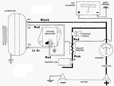
Humidity, heat, and vibration result in corrosion and poor connections, therefore the intent of the following measurement is to verify there is only a small voltage loss from the battery to the Voltage Regulator/Ballast Resistor/Ignition Control Module. Problems do to poor connections are more common as time passes. - At ballast resistor, connect voltmeter "+" lead to either red lead connector ("Ign 1" input). Connect voltmeter "-" to ground
- Set Ignition Switch ON; Engine OFF; Lights OFF; Accessories OFF; BATT. DUAL/MOM
Switch in Middle position
-
Measured Voltage should be within 0.5VDC of the Battery Voltage measured above.
Items to check if incorrrect:- Battery cable connectors (both ends of Positive and Negative connectors).
- Fusible Links at Starter Solinoid
- Engine to frame grounding leads.
- Ignition Switch and cabling (including connectors like at base of steering wheel)
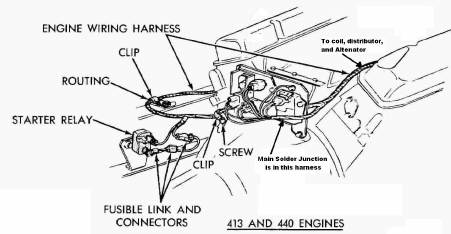
- Primary solder connection in wiring harness (see rear of engine wiring harness drawing)
- Start Engine (Lights OFF; Accessories OFF; BATT. DUAL/MOM Switch in Middle position) and increase RPM to 1250.
- Measured voltage should be between 13.8 and 15.0 VDC
- If Measured voltage is greater than 15.0, then Voltage Regulator is defective. Replace Voltage Regulator.
- If Measured voltage is less than 13.8 or is fluctuating:
- Verify Voltage Regulator ground
- Verify connections and circuit conditions:
- Battery cable connectors (both ends of Positive and Negative connectors).
- Fusible Links at Starter Solinoid
- Engine to frame grounding leads.
- Ignition Switch and cabling (including connectors like at base of steering wheel)
- Primary solder connection in wiring harness (see rear of engine wiring harness drawing)
- Set Ignition Switch OFF; Lights OFF; Accessories OFF; BATT. DUAL/MOM Switch in Middle position
- Verify supply voltage to Voltage Regulator: Disconnect connector from Voltage Regulator and verify pins on Voltage Regulator and the connector are in good condition.
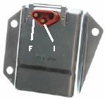
- Connect Voltmeter "+" to "I" pin (red lead) of Voltage Regulator Wiring Harness Connector. Connect "-" to ground
- Set Ignition Switch ON; Engine OFF; Lights OFF; Accessories OFF; BATT. DUAL/MOM Switch in Middle position
- Verify measured voltage is within 0.5VDC of Battery Voltage
- If the voltage is less than 0.5VDC than battery voltage, then there is a bad connection between the connector pin and the primary solder junction in the wiring harness.
- Set Ignition Switch OFF; Lights OFF; Accessories OFF; BATT. DUAL/MOM Switch in Middle position
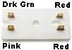
- Connect Voltmeter "+" to "F" pin (dark green lead) of Voltage Regulator Wiring Harness Connector. Connect "-" to ground
- Set Ignition Switch ON; Engine OFF; Lights OFF; Accessories OFF; BATT. DUAL/MOM Switch in Middle position
- Verify measured voltage is within 0.5VDC of Battery Voltage
- If the voltage is less than 0.5VDC than battery voltage:
- There is a bad connection (or open) in the field circuit between the connector pin and the primary solder junction in the wiring harness.
- Leave the Voltage Regulator disconnected.
- Set Ignition Switch OFF; Lights OFF; Accessories OFF; BATT. DUAL/MOM Switch in Middle position.
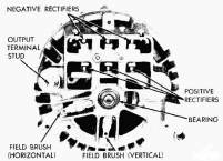 Disconnect the Dark Green FLD lead from the rear of the Altenator.
- Connect Voltmeter "+" to FLD pin on the rear of the altenator. Connect "-" to ground
- Set Ignition Switch ON; Engine OFF; Lights OFF; Accessories OFF; BATT. DUAL/MOM Switch in Middle position
- Verify measured voltage is within 0.5VDC of Battery Voltage
- If the voltage is within 0.5VDC of the battery voltage, then there is a bad connection in the Dark Green lead between the Voltage Regulator and Altenator. Repair the bad connection, Re-attach the connector to the Voltage Regulator and return to Step I.
- Set Ignition Switch OFF; Lights OFF; Accessories OFF; BATT. DUAL/MOM Switch in Middle position.
- Re-attach the Dark Green FLD lead to the rear of the Altenator.
- Disconnect the Red FLD lead from the rear of the Altenator.
- Connect Voltmeter "+" to Red FLD lead connector (B+ to altenator) removed from the altenator. Connect "-" to ground
- Set Ignition Switch ON; Engine OFF; Lights OFF; Accessories OFF; BATT. DUAL/MOM Switch in Middle position
- Verify measured voltage is within 0.5VDC of Battery Voltage
- If the measured voltage is within 0.5VDC of Battery Voltage, then the field circuit in the Altenator is open. Replace Altenator, re-attach all connectors, and return to step I
- There is a bad connection in the Red FLD lead between the altenator and the primary solder junction in the wiring harness. Repair the bad connection, Re-attach all connectors, and return to Step I.
- Set Ignition Switch OFF; Lights OFF; Accessories OFF; BATT. DUAL/MOM Switch in Middle position
- Re-attach Voltage Regulator Wiring Harness Connector to Voltage Regulator.
- Connect Voltmeter "+" to B+ terminal on the rear of the altenator. Connect "-" to ground
- Verify measured voltage is within 0.5VDC of Battery Voltage
- If voltage is not within 0.5VDC of Battery Voltage, then there is a bad connection or component (fusible link, Battery Solinoid Relay, etc.) between the B+ alternator terminal and the battery. Use the appropriate wiring diagram to trace the signal path back to the battery.
- This completes all 'cold' checks. If the measured charging system voltage is not between 13.8 and 15.0 VDC or is fluctuating then teither the Altenator or Voltage Regulator is defective. Most of todays Auto Supply houses can check an altenator so, remove the alternator and have it bench tested. If OK, then replace the Voltage Regulator otherwise replace the Altenator
- Replace/Repair defective components and return to step I
Warning
+12VDC is always present at the B+ terminal of the altenator. If there is a need to disconnect the connector from the B+ terminal then disconnect the battery cables from all batteries to prevent a hazardous situation.Note:
73 and earlier chassis has the B+ output of the altenator routed through the ampmeter in the dash. From there it goes back to the 'B' terminal of the Starter Solinoid via a fusible link at the solinoid.
74 and later (new style dash) routes the B+ output of the altenator directly to the 'B' terminal of the Starter Solinoid via a fusible link. The 74 and later new style dash uses a shunt style ampmeter circuit rather than applying full current through the dash. - Verify Voltage Regulator ground
- While monitoring the Voltage at the Ballast Resistor, One by one turn on lights and accessories.
- Verify a nominal voltage of 14.1 VDC is maintained.
- If a nominal voltage of 14.1 VDC cannot be maintained as the additional loads are added, then the either the altenator has a low output or the Voltage Regulator is breaking down. Most of todays Auto Supply houses can check an altenator so, remove the alternator and have it bench tested. If OK, then replace the Voltage Regulator otherwise replace the Altenator