GENERAL INFORMATION
These tandem master cylinders used on M300 (Late), RM300, M400 [RM350], M500 [RM400], and
M600 models are of the compensating type with reservoirs cast integrally. They consist of
front and rear pistons in tandem, each piston outlet supplies either front or rear brake
assemblies only. Piston outlets supplying drum brakes will require a residual valve to be
installed.
NOTE:Service procedures for these master cylinders are essentially the same, except
where noted.
NOTE: As shown below, outlets are reversed on certain models however on disc
brake installations, the large reservoir will always feed the front Disc brakes and the
small reservoir will feed the rear Drum brakes:
|
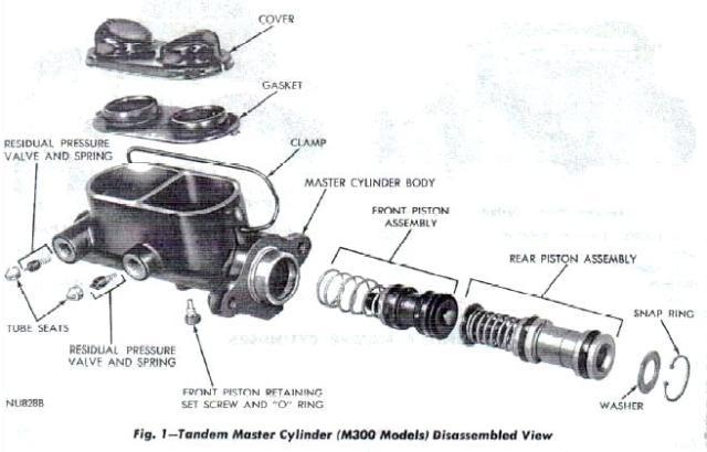
Fig. 1
1971-73 M300 (Late) models:
- Front outlet to rear drum brake assemblies.
- Rear outlet to front drum brake assemblies.
- Residual Valves are installed in each outlet port.
- Single Bendix Master-Vac based system
- Master cylinder push rod is part of the booster assembly.
|
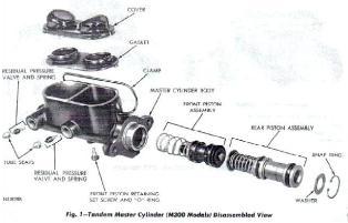
Figure 1
|
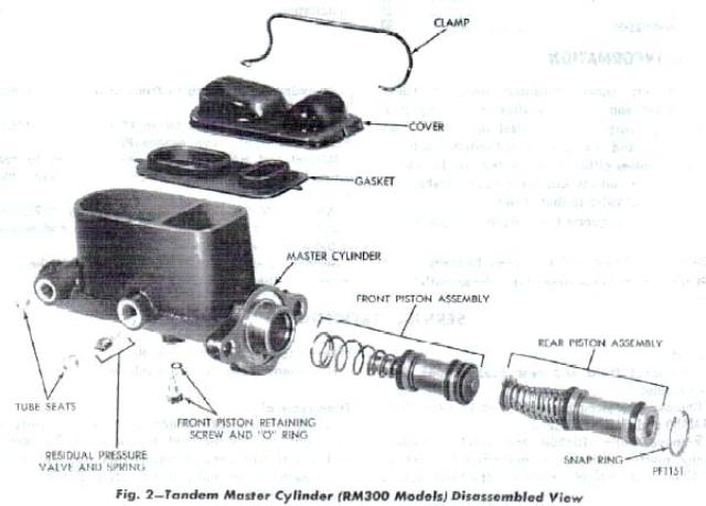
Fig. 2
1974-78 M300 [RM300] models:
- Front outlet (large reservoir) to front disc brakes.
- Rear outlet (small reservoir) to rear drum brakes.
- Residual Valve is installed in rear outlet port.
- Master cylinder push rod is part of the booster assembly.
- Single Bendix Master-Vac based systems
|
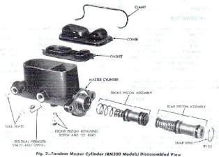
Figure 2
|
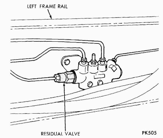
Fig. 3
1973-74 RM350 and RM400 models
1974-75 M400/M500 Models:
- Front outlet (small reservoir) to rear drum brakes.
- Rear outlet (large reservoir) to front disc brakes.
- Residual Valve is installed in front outlet port.
- Dual Bendix Hydro-Vac based Systems
|
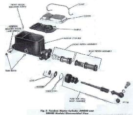
Figure 3
|
Fig. 3a
1979 and Later M300
1976 and Later M400, M500, and M600:
|
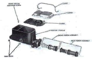
Figure 3a
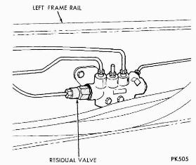
Figure 3b
|
SERVICE PROCEDURES
|
Removal
- Disconnect front and rear brake tubes from master cylinder.
- RM350/RM400 models:
- Remove bolt securing push rod to pedal linkage.
- Remove bolts attaching master cylinder to mounting bracket
- M300/RM300/M400/M500/M600 models: Remove nuts attaching master cylinder to brake booster (Fig. 9).
- Remove assembly from vehicle.
|
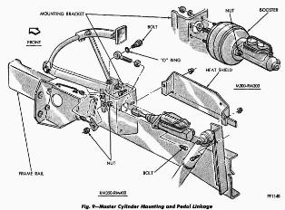
Figure 9
|
Disassembly
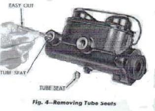
- After cleaning outside of cylinder, insert an "easy out" in tube seat and tighten
firmly. Tap gently on tool with hammer and remove tube seat (Fig. 4).
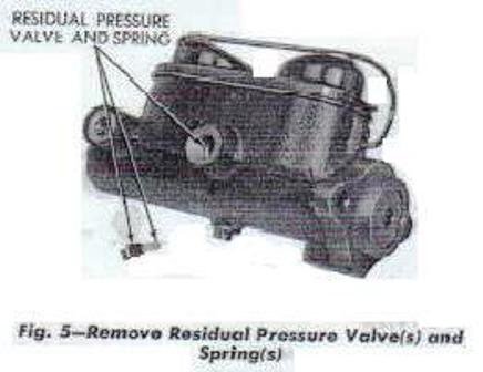
- Remove residual pressure valve (Fig. 5).
- 1971-73 M300 (Late; Front Drum): two valves
- 1974-78 M300 [RM300]: one valve, rear outlet
- 1973-74 RM350/RM400; 1974-75 M400/M500: one valve, front outlet.
- 1979 and Later M300; 1976 and Later M400/M500/M600: None .
- Slide clamp off cover, remove cover and gasket and drain brake fluid from cylinder.
- Using snap ring pliers, remove snap ring from open end of cylinder (Fig. 6).
- RM350/RM400 models: Slide push rod and washer out of cylinder.
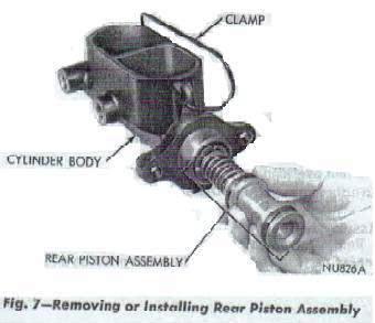
- After removing front (secondary) piston retaining screw carefully remove rear (primary)
piston assembly (Fig. 7).
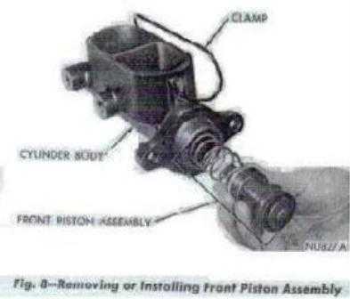
- Slide front (secondary) piston assembly from cylinder (Fig. 8).
- Clean all parts in a suitable solvent and blow dry with compressed air. Wash the cylinder
bore with clean brake fluid and inspect for scoring or pitting. Master cylinder bore walls
that have light scratches or show signs of corrosion, can usually be cleaned with crocus
cloth. However, cylinder bores that have deep scratches or scoring may be honed, providing
diameter of bore is not increased more than .002 inch.
If master cylinder bore does not clean up at .002 inch when honed, the master cylinder
should be discarded and a new one installed.
If master cylinder pistons are badly scored or corroded, replace them with new ones. All cups
and seals should be replaced when conditioning a master cylinder.
When overhauling a master cylinder, use all parts furnished in repair kit.
Discard all used rubber parts.
|

Figure 4
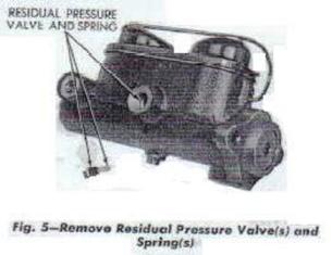
Figure 5
|
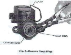
Figure 6
|
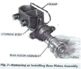
Figure 7
|
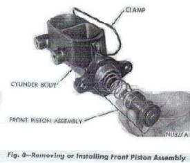
Figure 8
|
Assembly
Before assembling the master cylinder dip all component parts in clean brake fluid and place
on a clean shop towel or paper (dry assembly can damage seals).
- Generously coat bore of master cylinder with brake fluid.
- Carefully slide front (secondary) piston assembly into cylinder body, (Fig. 8).
- Slide rear (primary) piston assembly into cylinder body (Fig. 7).
- Compress pistons and install and tighten front piston retainer screw.
- RM350/RM400 models: Hold push rod and washer in position and install snap ring.
Position boot, if so equipped.
- If applicable, install residual pressure valve(s) and spring(s) in outlet port(s) and install tube
seats firmly.
Bleeding
Before installing master cylinder on vehicle it must be bled on bench as follows:
- Clamp master cylinder in a vise and attach bleeding tubes Tool C-4029.
- Fill both reservoirs with approved brake fluid.
- Using a push rod, depress the rod slowly and allow the pistons to return under spring pressure. Do this
several times until all air bubbles are expelled.
- Remove bleeding tubes from cylinder and install gasket and cover. (As tubes are moved,
fluid remaining in tube will siphon out.)
- Install cover clamp and remove master cylinder from vise.
Installation
- RM350/RM400 models: Position master cylinder on mounting bracket.
- M300/RM300/M400/M500/M600 models: Position master cylinder on booster face.
- Install attaching nut (or nut and bolt) and tighten to 30 foot pounds.
- RM350/RM400 models: Connect push rod to pedal link and tighten nut to 30 foot pounds.
- Connect front and rear brake tubes and tighten securely.
|
Figure 8
Figure 7
|