Dave's Place
Hydro-Boost Brake Systems
Bendix Hydraulic Brake BoosterIn 1968, there were indications that newer power brake systems may be required in the near future. Alterations or improvements to existing vacuum suspended boosters would be required to meet new safety regulations that would govern vehicle stopping distances and brake pedal effort. Proposed vehicle emission controls posed additional problems for vacuum boosters in the form of reduced engine vacuum and higher under hood operating temperatures. |
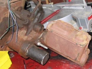 Dodge M400 Hydro-Boost with Master Cylinder Attached |
|
In 1974 Bendix introduced a hydraulic power brake booster patented under then name "Hydro-Boost"
(Figure 1). Hydro-Boost features:
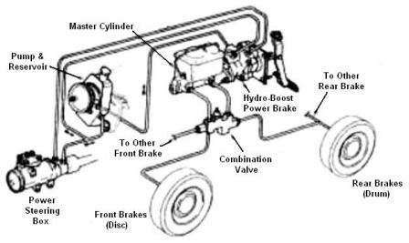 Figure 2 A sliding spool valve in the Hydro-Boost controls fluid flow from the power steering pump under all operating conditions. During brake application the flow to the power steering gear remains constant and the spool valve diverts fluid under pressure to the boost cavity of the Hydro-Boost. Because of the spool valve action, the power brake unit and power steering unit do not interfere with one another whether at rest or in use. Three lines are connected to the power section. One of line directs pressure from the power steering pump to the Hydro-Boost. A second line connects to the steering gear. The third is a return line back to the steering pump reservoir. A fourth line would be used in conjunction with a remote accumulator. Should normal steering pump pressure be interrupted (i.e. stalled engine, ruptured steering hose, or broken pump drive belt) a reserve pressure system will be activated. The reserve system of an accumulator, check valve assembly, and a dump valve assembly Three styles of accumulators have evolved since the introduction of the Hydro-Boost. A spring loaded design (Figures 3 and 4) was used from 1974 - 1978. In 1981 the Hydro-Boost II system was introduced which incorporated the accumulator into the power piston assembly. This made the assembly more compact and lighter. 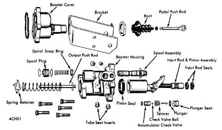 Figure 3 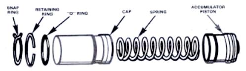 Figure 4 |
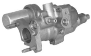 Figure 1 |
OperationReleased PositionWith the engine running, brake pedal unapplied, the majority of pump pressure is routed through the power section to the steering gear.Applied PositionUpon brake application, the input rod and power piston move slightly forward. A pivot arm connects the spool valve to the power piston and input rod assembly. Additional pedal movement forces the spool valve forward into the bore. This action results in diverting additional pump pressure into the cavity behind the power piston to build hydraulic pressure in this area. The resulting pressures move the power piston and output rod forward to activate the master cylinder.ReleasingRelease of the brake pedal allows the spool valve return spring to push the spool valve back to it's normal release position. Excess fluid back of the power piston returns to the steering pump reservoir through the return line.Reserve SystemThe reserve system will be activated in the event of an engine stall, ruptures steering hose, or broken pump drive belt. Increased pedal travel, due to pressure loss, will require further travel of the spool valve. The accumulator dump valve will be mechanically opened, permitting stored pressure (approximately 1,000 - 1500 PSI) to bleed into the power piston cavity. Two to three assisted applications (Hydro-Boost I), one to two (Hydro-Boost II) will be provided by accumulator pressure reserve.Manual Brake ApplicationDesign of the Hydro-Boost permits the vehicle operator to apply the brakes manually (without power assist) if fluid under pressure is not available from the steering pump or reserve system. |
|
|
CAUTION Prior to working on the Hydro-Boost unit, depress and release brake pedal several times (with engine off) to be sure that all pressure is discharged from the accumulator prior to disconnecting any lines or hoses. |
|
Hydro-Boost Repair and Maintenace Document Link |
|