Dave's Place
RV Electrical Systems
|
1970's Progressive Dynamics (PD) Progressive Dynamics Discontinued Transfer Switches Modern Electrical System Setup |
||
1970's Progressive Dynamics (PD)During the 1970's Winnebago used Progrssive Dynamics Power Converters and Electrical Control Centers. These systems are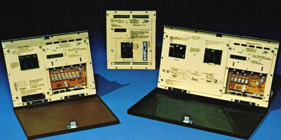 |
||
*** Models ***Progressive Dynamics is discontinuing support for these older products. They are providing customers with owners manuals and troubleshooting information for the discontinued models. Unfortunately they will no longer be able to provide support for these models. They do however still have some parts available for sale (PD Parts) |
||
Power Converter Owners ManualPD684 and PD685PD688 PD694, 696, 698, 699, 6995 PD703 thru PD705 PD707 and PD708 PD709 PD710 and PD711 PD712 PD6800 series PD6900 (Single) PD6900 (Dual) PD9000 series |
Electrical Control Center Owners Manual PD720Q thru PD723Q  PD731 thru PD735  PD731Q thru PD738Q PD743 thru PD746  PD7220 and PD7231  PD7500 and PD7700 Series  PD8000 series |
Trouble shooting / Service ManualsPD9000 series710778.pdf Covers: PD720Q thru PD723Q, PD731Q thru PD738Q, PD731 thru PD733, PD743 thru PD746, PD753 thru PD756, PD761Q thru PD768Q, PD773 thru PD776, 7220, 7231, 7338, 7348, 7648 and 7655. |
*** Components ***Reduces the 120 VAC from the Shore Power or Generator down to approximately 13.8 Volts AC (Alternating Current) at its secondary output. Diode Rectifier Converts the 13.8 Volts AC from the Transformer secondary output to approximately 13.8 Volts DC (Direct Current). Relay Automatically disconnects the RV Battery from the 12-volt RV circuits and then connects the 13.8-volt power to the RV 12-volt circuits when Shore Power is connected to the RV. Battery Charger Circuit Board Senses the battery voltage and then provides a signal to the SCR (Silicon Controlled Rectifier) to turn it ON, which in turn supplies charging current to the RV Battery. The charger board is equipped with an LED (Light Emitting Diode) that indicates the charging status as follows. (LED optional on some units).
This is basically an electronic switch that is controlled by the circuit board. It is turned ON when the battery needs charging current and is turned OFF, when the circuit board senses the battery is charged. Current Limiting Resistor This resistor limits the amount of charging current that can be delivered to the battery. |
||
*** 1970's PD Operation *** |
||
No AC power available to the RVThe RV battery is supplying 12-volt power (Red Arrows ) to the RV branch circuits through the N.C. (Normally Closed) contacts of the relay. See figure 2 below for operation when AC power is applied. The Isolated Circuits for the Radio, TV or Stereo are connected directly to the battery positive terminal. (Green Arrows). |
|
|
AC power is available to the RVThe Transformer reduces the 120 VAC down to 13.8 VAC (Alternating Current). It is then fed through the Diode Rectifiers, which convert this AC Voltage to 13.8 VDC. This DC power is also fed to the Relay Coil, which in turn pulls down the center arm of the Relay so that it makes contact with the lower N.O. (Normally Open) contacts. Now the converter feeds DC Power to the branch circuits (red arrows). This action also disconnects the RV battery from the branch circuits and places it on charge (blue arrows). Note that the DC power for the Isolated Circuits is always coming directly from the battery or the charging circuit when 120 VAC power is applied to the RV (green arrows). |
|
|
Progressive Dynamics Discontinued Transfer Switches |
||
Modern Electrical System Setup
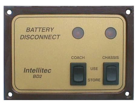
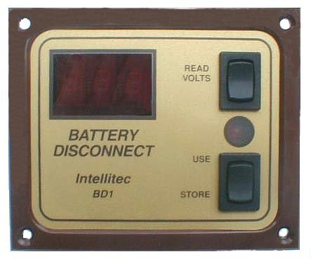
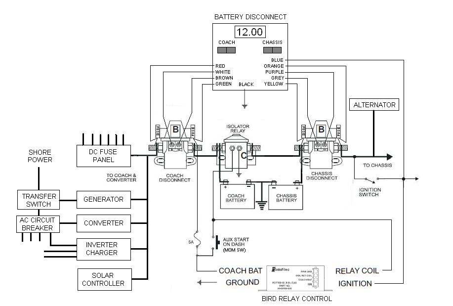
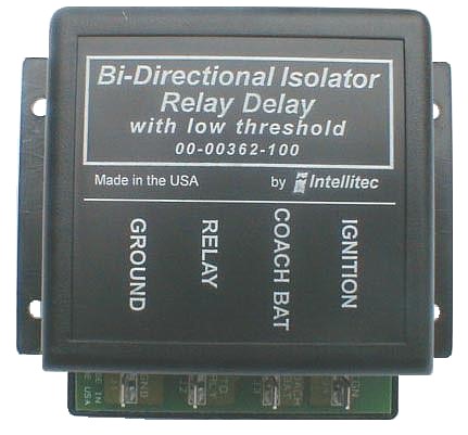
Intellitec |
||