Dave's Place
Main Circuit Board (second generation)

Before working with electricity, visit the electrical safety page.
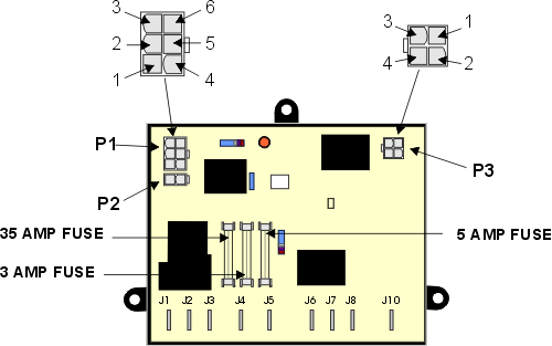
The main circuit board controls and activates all of the heat sources (AC, DC, and gas) of the refrigerator. It requires 12 volt power at all times for the refrigerator to work on any heat source. The main circuit board takes its settings from the eyebrow board via a communication link and proceeds accordingly. It has the job of determining if AC is present, for example, and switching to gas if it's not. It directly controls the components of the gas system, and sends voltage directly to the 12 volt element and 120 volt element. The board shown below is a 3 way model. The 2 way version would not have terminal J1 and the 35 amp fuse.
Troubleshooting
Basically, troubleshooting the main circuit board entails a knowledge of what should happen when and testing
the input and output of the various connections on the board. See the various heat source sections (
AC, DC, and gas) for
troubleshooting the individual heat sources. If you suspect a communication problem between the main
board and the eyebrow board, you can check the voltages at plug P1. If you suspect a cable problem between
the two, you can check for voltages at P1 and at the eyebrow. Twelve volt
goes to the eyebrow from P1, pin 4 and returns through pins 1 and 3 in P1 when the eyebrow switch is
depressed to the "On" position. Knowing this and making corresponding tests at the eyebrow would test
the cable between them. There is no test for the brown wire (pin 6, communication link). However, from
experience, the eyebrow boards seldom fail. In a toss up, go for the lower, main board.
The Dinosaur brand P-711 is a replacement for the main circuit board on these models.
Terminal Connections
|
|
Plugs P1 and P3 wiring:
|
| ||||||||||||||||||||||||||||||||||||||||||||||||
Dometic Electronic System (second generation)
RV Refrigerator Home
This RV refridgerator information was originally located on rvmobile.comRV Mobile Inc. 11715 HWY 99, Everett, WA 98204
The owner of RV Mobile Inc. apparently suffered a heart attack and the original website was shut down.
It has been reposted here to preserve this wealth of information RV refridgerator information.

