Dave's Place
8700 Series PC Board
Before attempting any repairs or testing, check out the electrical safety pages.

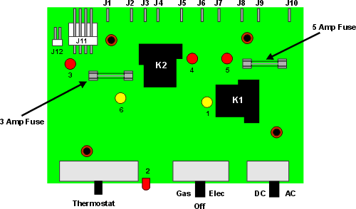
The PC Board controls and activates all of the heat sources ( AC, DC, and gas) of the refrigerator. It requires 12 volt power at all times for the refrigerator to work on any heat source. It provides voltage to the Ignition Control Module when gas is selected, and sends voltage directly to the 12 volt element and 120 volt element, when those heat sources are selected. The board shown below is for a 3 way model of the 8700 series. The 2 way version would not use terminals J3 and J6.
The PC board on the 8700 series is an all in one board, incorporating the functions of the eyebrow board and Power Supply Board used on other models into the one board. This eliminates a lot of connection problems. The setup was pretty nifty, but short lived, probably because the controls were at the bottom of the refrigerator.
|
|
Troubleshooting the PC Board is a matter of testing what should come in and go out of the board. See the table above for information on that. Also, the fuses on the board should be tested. Please note that the fuse for the 12 volt heat element is not on the board, but is an inline fuse between the board and the heat element. This board also has a few L.E.D. indicators on it that can help in troubleshooting. They are shown in the table to the right.
Norcold Electronic System (second generation) Home
RV Refrigerator Home
This RV refridgerator information was originally located on rvmobile.comRV Mobile Inc. 11715 HWY 99, Everett, WA 98204
The owner of RV Mobile Inc. apparently suffered a heart attack and the original website was shut down.
It has been reposted here to preserve this wealth of information RV refridgerator information.