Dave's Place
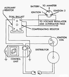
Dodge Electronic Ignition
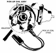
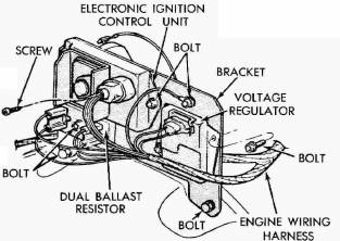
Components
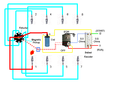
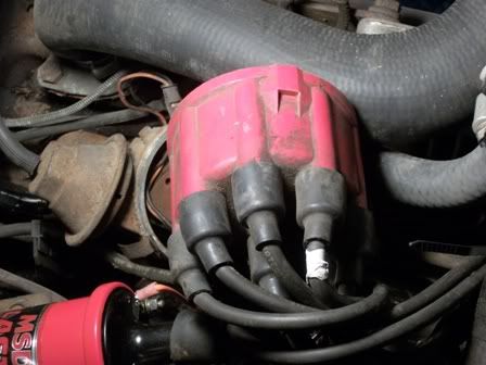
This system consists of a special pulse-sending distributor, an electronic control unit, a two-element ballast resistor, and a special ignition coil. The distributor does not contain breaker points or a condenser, these parts being replaced by a distributor reluctor and a pick-up unit. It was used from then on in all Dodge Class A motorhomes (M300-M600)
|
||

|
|
|

|
||
|
|
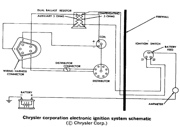
Ballast Resistor
|
|
|
|
Coil
|
|
|
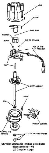
Distributor
|
|
|
|
Electronic Control Module (ECM)
|
|
Operation
The ignition primary circuit is connected from the battery, through the ignition switch (I1), through the primary side of the ignition coil, to the control unit (pin 2) where it is grounded.
The secondary circuit is the same as in conventional ignition systems: from the secondary side of the coil, the coil wire to the distributor, the rotor, the spark plug wires, and the spark plugs.
The magnetic pulse distributor is also connected to the control unit. As the distributor shaft rotates, the distributor reluctor turns past the pick-up unit. As the reluctor turns past the pick-up unit, each of the eight teeth on the reluctor pass near the pick-up unit once during each distributor revolution (two crankshaft revolutions since the distributor runs at one-half crankshaft speed). As the reluctor teeth move close to the pick-up unit, the magnetic rotating reluctor induces voltage into the magnetic pick-up unit. This voltage pulse is sent to the ignition control unit from the magnetic pick-up unit (pins 4 and 5).
When the pulse enters the control unit, it signals the control unit to interrupt the ignition primary circuit. This causes the primary circuit to collapse and begins the induction of the magnetic lines of force from the primary side of the coil into the secondary side of the coil. This induction provides the required voltage to fire the spark plugs.
The advantages of this system are:
- The transitors in the control unit can make and break the primary ignition circuit much faster than conventional ignition points.
- A higher primary voltage can be utilized since this system can be made to handle higher voltage without adverse effects, whereas ignition breaker points cannot.
- The quicker switching time of this system allows longer coil primary circuit saturation time and longer induction time when the primary circuit collapses. This increased time allows the primary circuit to build up more current and the secondary circuit to discharge more current.
The point at which each spark plug fires is variable and is controlled by:
- Initial Timing Advance setting
- Mecanical Advance
- Vacuum Advance
Initial Timing Advance setting
This is the reference point upon which all engine timing is based. Timing advance is required because it takes time to burn the air-fuel mixture. Igniting the mixture before the piston reaches top dead center (TDC) will allow the mixture to fully burn soon after the piston reaches TDC. If the air-fuel mixture is ignited at the correct time, maximum pressure in the cylinder will occur sometime after the piston reaches TDC allowing the ignited mixture to push the piston down the cylinder with the greatest force. If the ignition spark occurs at a position that is too advanced relative to piston position, the rapidly expanding air-fuel mixture can actually push against the piston still moving up, causing detonation and lost power. If the spark occurs too retarded relative to the piston position, maximum cylinder pressure will occur after the piston is already traveling too far down the cylinder. This results in lost power, high emissions, and unburned fuel.
1973 (Electronic Ignition)
318 - 2.5 +/- 2.5 Degress BTDC
413 - 5.0 +/- 2.5 Degress BTDC
440 - 7.5 +/- 2.5 Degress BTDC
1974 and later
Typically the same as 1973 but refer to the Emissions Label on the Valve Cover.
Note:
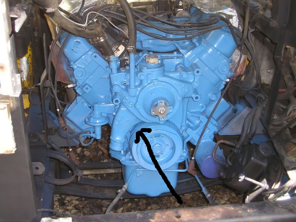
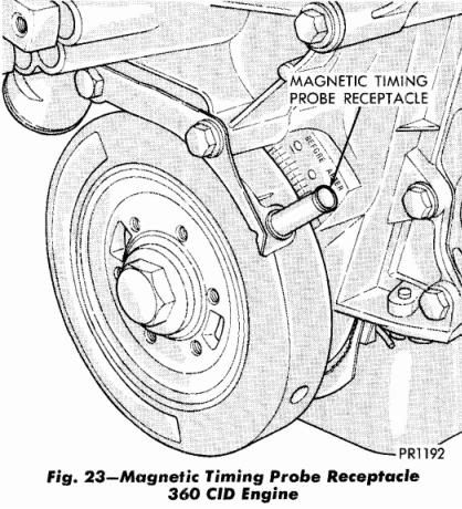
Seeing the timing marks and reference plate on a 440-3 can be difficult. You normally have to turn the front wheels
to the left and get up inside the right front wheel well to see the timing marks. Even then, you may have to unbolt
the radiator overflow container and move it out of your way to see the timing marks.
440-3 Timing tab mounted on timing cover:
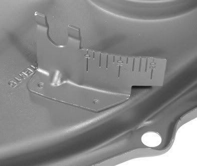
Location of timing tab on front of engine (360 tab is located on drivers side of water pump):
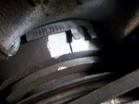
Close up of a 440-3 Timing tab aligned with timing marl on harmonic balancer:
Rotor position with #1 cylinder at TDC on compression stroke (pointing at alternator):
Relationship of #1 plug wire (white tape) to distributor cap hold down clamp:
79 and later 440-3 timing tab:

360 timing tab:
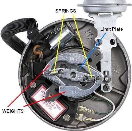
Mecanical Advance
Ignition timing has to become increasingly advanced (relative to TDC) as the engine speed increases so that the air-fuel mixture has the correct amount of time to fully burn. As the engine speed increases, the time available to burn the mixture decreases but the burning itself proceeds at the same speed, it needs to be started increasingly earlier to complete in time. An increasing mechanical advancement of the timing takes place with increasing engine speed. This is possible by using the law of inertia. Weights and springs inside the distributor rotate and affect the timing advance according to engine speed by altering the angular position of the timing sensor shaft with respect to the actual engine position. This type of timing advance is also referred to as centrifugal timing advance. The amount of mechanical advance is dependent solely on the speed at which the distributor is rotating.
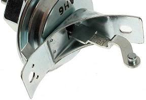
Vacuum Advance
The second method used to advance the ignition timing is called vacuum timing advance. It increases fuel economy
and driveability, particularly at lean mixtures. A vacuum chamber on the side of the distributor automatically
varies the instant at which the spark occurs as a function of manifold vacuum. Vacuum advance provides the additional
advance that is needed when the engine is operating at part throttle. At part throttle less air-fuel mixture gets
into the cylinders and the mixture takes longer to burn after it is ignited. Because the mixture burns more slowly,
the piston will be past top dead center and moving down before the mixture has a chance to burn and produce high
power. As a result much of the power in the fuel will be lost. The vacuum advance mechanism consists of a flexible
spring-loaded diaphragm connected by a linkage to a plate on which the magnetic pick-up is mounted (breaker plate
on which the points are mounted for non-electronic ignition systems). The sealed side of the diaphragm is connected
by a tube to the carburetor . The throttle valve (butterfly) is below the vacuum passage (port) in the carburetor
air horn so there is no vacuum advance when the engine is idling because the throttle is closed. However, when the
throttle is partly open, intake manifold vacuum pulls the diaphragm in and this causes the breaker plate to rotate a
few degrees and advance the timing . With wide-open throttle there is very little vacuum in the intake manifold so
there will be no vacuum advance. In most instances the vacuum advance is disconnected before checking the timing and
point gap (non-electronic ignition systems).
In summary:
- No Vacuum Advance at idle.
- No Vacuum Advance at wide open throttle.
- Vacuum Advance system is intended for emissions control, driveability, and fuel economy.
Vacuum advance plate action:

In response to emission control requirements, in 1974 Dodge added a emission control sytem which senses engine temperature in order to regulate the vacuum advance system when the engine is hot or cold. This system increases the advance when the engine is cold by allowing engine manifold vacuum to also be used when the engine is cold. Once the engine is warmed up, normal ported vacuum is used. At low temperature the advance allows the enriched warm-up mixture to burn more completely, providing better and cleaner cold-engine running.
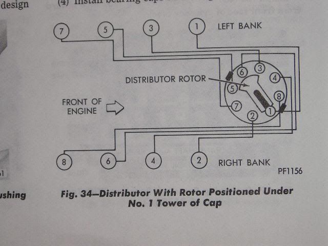
Firing Order
For all engines 1-8-4-3-6-5-7-2
Left side cylinders are numbered (from front) 1-3-5-7
Right side cylinders are numbered (from front) 2-4-6-8
Firing order diagram fro 440-3 engine:
Start vs Run
Start
When the ignition key is placed in the START position, battery voltage is supplied to both the I1 and I2 leads.
The I1 lead provides voltage to the AUX side (5.0 Ohm) of the Ballast Resistor and to pin 1 (primary power input)
of the ECM. The output of the AUX resistor is applied to ECM pin 3 and is used for electronic circuit stablization.
The I2 lead provides voltage to the output side of the Compensating Resistor (0.5 Ohm) section of the Ballast Resistor
therfore the Compensating Resistor is bypassed during starting.
Full battery supply voltage is then applied to the plus (+) side of the Coil. The minus (-) side of the coil is
connected to pin 2 of the ECM. The ECM (via pin 2) controls electrical current flow through the coil. Electrical
current will flow through the coil until the the distributor pick-up (ECM pins 4 and 5) signals it is time to fire
the spark plug. The ECM then shuts OFF the current flow which causes the magnetic field in the coil to collasp.
This results in a high voltage pulse being routed to the spark plug via the coil wire, distributor cap, rotor and
spark plug wire. After a predetermined amount of time (designed into the ECM circuitry) the ECM will turn the
current back ON to the coil.
Run
When the ignition key is placed in the RUN position, voltage is supplied to just the I1 lead.
The I1 lead provides voltage to the AUX side (5.0 Ohm) and the Compensating side (0.5 Ohm) of the Ballast Resistor
and to pin 1 of the ECM. Since there is no voltage from the igniition switch on I2, the voltage (reduced) applied
to the coil is via the Compensating Resistor. The remaning operation is identical to the START position.
CAUTION
Bypassing (jumpering around) the Compensating Resistor for extended periods of time will
damage the ECM.
Carry a spare Ballast Resistor in your on-board toolkit instead.
Notes:
- The Ballast Resistor is a high failure item. Most people carry a spare Ballst Resistor with them.
-
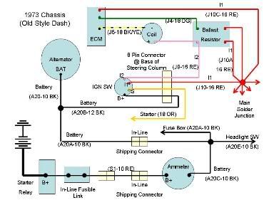 Corroded wiring connectors and solder joints will reduce voltage to the ignition circuitry resulting in hard
starting and phantom problems. In the wiring harness drawing above, take note of the location of the Major
Solder Junction reference as it is the main distribution point for ignition and charging circuitry.
Corroded wiring connectors and solder joints will reduce voltage to the ignition circuitry resulting in hard
starting and phantom problems. In the wiring harness drawing above, take note of the location of the Major
Solder Junction reference as it is the main distribution point for ignition and charging circuitry.
You can see by this drawing of a 1973 chassis, there are many connections and solder joints between the battery and the Ballast Resistor/ECM Module. Corrosion, overstressed wiring (high current), and age all factor in resulting in voltage drops. The in-line fusible links located at the starter relay weaken with time due to current draw. - For reference, basic operation of the Multiple Spark Discahrge (MSD) system is based on the same principles as the MOPAR system. Hookup is a little different (no ballast resistor) and the MSD fires a spark plug multiple times but the system is still triggered by a pick-up sensor and controls current flow through the coil. The deference is that it turns the coil off and on multiple times for each firing pulse.
- Useful Tools
- Actron CP7677 Auto Troubleshooter
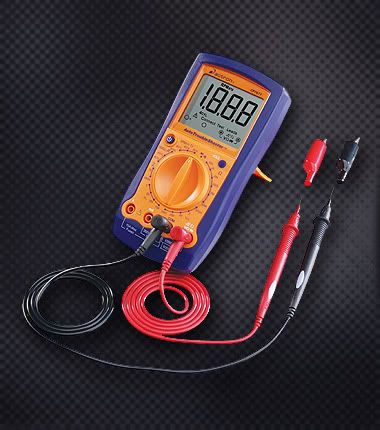
- Tests engine RPM and dwell
- Measures AC/DC voltage, DC current and resistance
- Tests continuity, wiring and diodes
- Tests starting & charging, ignition and fuel delivery systems
- Actron CP9087 Ignition Module and Sensor Testor

- Test ignition modules (ECM) and igniters
- Tests sensors including O2, MAP, MAF, knock and crankshaft sensors (ie: Distributor pickup sensor)
- Tests continuity, wiring and diodes
This tool is sort of the missing link many are looking for.
Allows you to check the ECM (Section 3 using the Magnetic Reluctance Pick-up hookup on page 3-9 of the tester manual). Allows you to check the Distributor Pick-up sensor (Section 2, page 2-46 of the tester manual, Magnetic Reluctance version)
- Actron CP7677 Auto Troubleshooter
Tuning
We spend a lot of time changing the plugs, setting the timing and adjusting the carburetor based on manufactures documentation however, if it doesn't seem to work out correctly, do we really understand why? As time goes by, technology has progressed, some methods and procedures have changed (or need to be changed), and others are still as valid today as they were when they were written down a almost a half century ago. Even our beloved Pharaoh is not immune to the mysteries of tuning. The PO of his Chariot was terrified of electronic ignition and converted the 440-3 in his rig to points based ignition. Mark acquired a stock replacement electronic ignition system which I helped him install several years ago. Mark had also replaced the Thermoquad carburetor with a 750 CFM Edelbrock Carburetor. At that time, there was a still a whole lot of information I didn't know and we never did get his rig running correctly. I believe the problems we faced then still plague him today. Well, now that I have researched and learned a lot more, I hope that the information I provide here will assist him and many others overcome the Mysteries of Tuning and be able to feel the warm satisfying deep throated rumble of a well mannered toy box.
I have a Dodge based rig therefore most of my research efforts have been Dodge oriented. Even so, much of this information can be translated to all manufacturers (Dodge, Ford, GM, etc.) and portions will be unique to a given chassis.
I will attempt to meld the old with the new and hopefully provide many here with a working level insight on how to keep our beloved toy boxes running smooth and perky. From there, I will dabble in the art of new Technology (MSD and alternative ignition technology).
Reference
- Timing is everything [MoPar Muscle Magazine April 98 Article]
- How to Rebuild and Modify Carter/Edelbrock Carburetors
- A Carter Thermo-Quad Guide
- Carter Thermoquad Service Procedures - 1972 [Old Car Manual Project]
- Rochester Quadrajet Service Manual (1980-1986) [Old Car Manual Project]
- Ported Vacuum vs. Manifold Vacuum
A Little Background
Formulating a precision Air/Fuel (A/F) mixture and igniting it at the correct time in a 4-cycle engine, or even a 2 cycle/diesel engine for that matter, is a scientific art. There I have said it. Now we all can set back and admit we could never grasp the mysteries of tuning.
Wrong
Now you didn't think I would let you get off that easy did you?
Seriously, it doesn't matter whether it's todays computerized turbocharged demon or a 1960's era gem restored to original, the basic principles are the same. Sure, computer programs have been substituted for centrifugal advance, MAP sensors for vacuum advance cans, knock sensors for "human ear detonation sensors", and timed injectors for carburetors; the net result is that the basic principles are still the same. The manufacturers engineers hid most of this from you so that they (or in many regions you) could repeatably pass emissions inspection. For our older rigs however we are resigned to working with what was installed in the 70's and 80's which may only contain bits and pieces of todays emissions control systems. The artful part, or rather what gets lost as time marches on, is an understanding of the basics and how the engineers modified the systems in order to meet the evolving emissions requirements.
Basic Engine Requirements
At idle and cruising speeds, the ideal Air/Fuel mixture is 14.7 parts air to 1 part atomized fuel. During acceleration (power mode) the A/F mixture varies from 12.5 to 14.7 depending on engine speed and load. Carburetor manufacturers implemented many circuits to accomplish all this which I will go into later. In an attempt to adapt carbureted systems to meet evolving emissions requirements, design engineers implemented many band-aids (ported vacuum, EGR, air pumps, etc.) to meet the new emissions requirements. Fortunately, much of that research was used in the development of computerized engine management. Since the early to mid 1980's, a O2 sensor has been used to regulate either a carburetor (last one was in a 1987 Subaru Justy) or fuel injection (either a Throttle Body [TBI] or Rail system) for idle and cruise mode operations. Prior to the implementation of the O2 sensor, Air/Fuel regulation was performed by a carburetor (Holley, Carter Thermoquad, Rochester Quadrajet, Edlebrock). Today, we can use the newer wideband O2 sensor technology to assist in the carburetor tuning process. While carburetor operation is a vital part of the tuning process, the ignition system has to be addressed first so, for now, just understand that part of the tuning process involves adjusting the A/F ratio based on the loads and requests being placed on the engine at any given moment.
The most important concept to understand is that lean mixtures, such as at idle and steady highway cruise, take longer to burn than rich mixtures; idle in particular, as idle mixture is affected by exhaust gas dilution. This requires that lean mixtures have "the fire lit" earlier in the compression cycle (spark timing advanced), allowing more burn time so that peak cylinder pressure is reached just after TDC for peak efficiency and reduced exhaust gas temperature (wasted combustion energy). Rich mixtures, on the other hand, burn faster than lean mixtures, so they need to have "the fire lit" later in the compression cycle (spark timing retarded slightly) so maximum cylinder pressure is still achieved at the same point after TDC as with the lean mixture, for maximum efficiency.
The centrifugal advance system in a distributor advances spark timing purely as a function of engine rpm (irrespective of engine load or operating conditions), with the amount of advance and the rate at which it comes in determined by the weights and springs on top of the autocam mechanism. The amount of advance added by the distributor, combined with initial static timing, is "total timing" (i.e., the 34-36 degrees at high rpm that most SBC's like). Vacuum advance has absolutely nothing to do with total timing or performance, as when the throttle is opened, manifold vacuum drops essentially to zero, and the vacuum advance drops out entirely; it has no part in the "total timing" equation.
At idle, the engine needs additional spark advance in order to fire that lean, diluted mixture earlier in order to develop maximum cylinder pressure at the proper point, so the vacuum advance can (connected to manifold vacuum, not "ported" vacuum - more on that aberration later) is activated by the high manifold vacuum, and adds about 15 degrees of spark advance, on top of the initial static timing setting (i.e., if your static timing is at 10 degrees, at idle it's actually around 25 degrees with the vacuum advance connected). The same thing occurs at steady-state highway cruise; the mixture is lean, takes longer to burn, the load on the engine is low, the manifold vacuum is high, so the vacuum advance is again deployed, and if you had a timing light set up so you could see the balancer as you were going down the highway, you'd see about 50 degrees advance (10 degrees initial, 20-25 degrees from the centrifugal advance, and 15 degrees from the vacuum advance) at steady-state cruise (it only takes about 40 horsepower to cruise at 50mph).
When you accelerate, the mixture is instantly enriched (by the accelerator pump, power valve, etc.), burns faster, doesn't need the additional spark advance, and when the throttle plates open, manifold vacuum drops, and the vacuum advance can returns to zero, retarding the spark timing back to what is provided by the initial static timing plus the centrifugal advance provided by the distributor at that engine rpm; the vacuum advance doesn't come back into play until you back off the gas and manifold vacuum increases again as you return to steady-state cruise, when the mixture again becomes lean.
The key difference is that centrifugal advance (in the distributor autocam via weights and springs) is purely rpm-sensitive; nothing changes it except changes in rpm. Vacuum advance, on the other hand, responds to engine load and rapidly-changing operating conditions, providing the correct degree of spark advance at any point in time based on engine load, to deal with both lean and rich mixture conditions. By today's terms, this was a relatively crude mechanical system, but it did a good job of optimizing engine efficiency, throttle response, fuel economy, and idle cooling, with absolutely ZERO effect on wide-open throttle performance, as vacuum advance is inoperative under wide-open throttle conditions. In modern cars with computerized engine controllers, all those sensors and the controller change both mixture and spark timing 50 to 100 times per second, and we don't even HAVE a distributor any more - it's all electronic.
Now, to the widely-misunderstood manifold-vs.-ported vacuum aberration. After 30-40 years of controlling vacuum advance with full manifold vacuum, along came emissions requirements, years before catalytic converter technology had been developed, and all manner of crude band-aid systems were developed to try and reduce hydrocarbons and oxides of nitrogen in the exhaust stream. One of these band-aids was "ported spark", which moved the vacuum pickup orifice in the carburetor venturi from below the throttle plate (where it was exposed to full manifold vacuum at idle) to above the throttle plate, where it saw no manifold vacuum at all at idle. This meant the vacuum advance was inoperative at idle (retarding spark timing from its optimum value), and these applications also had VERY low initial static timing (usually 4 degrees or less, and some actually were set at 2 degrees AFTER TDC). This was done in order to increase exhaust gas temperature (due to "lighting the fire late") to improve the effectiveness of the "afterburning" of hydrocarbons by the air injected into the exhaust manifolds by the A.I.R. system; as a result, these engines ran like crap, and an enormous amount of wasted heat energy was transferred through the exhaust port walls into the coolant, causing them to run hot at idle - cylinder pressure fell off, engine temperatures went up, combustion efficiency went down the drain, and fuel economy went down with it.
If you look at the centrifugal advance calibrations for these "ported spark, late-timed" engines, you'll see that instead of having 20 degrees of advance, they had up to 34 degrees of advance in the distributor, in order to get back to the 34-36 degrees "total timing" at high rpm wide-open throttle to get some of the performance back. The vacuum advance still worked at steady-state highway cruise (lean mixture = low emissions), but it was inoperative at idle, which caused all manner of problems - "ported vacuum" was strictly an early, pre-converter crude emissions strategy, and nothing more.
What about the Harry high-school non-vacuum advance polished billet "whizbang" distributors you see in the Summit and Jeg's catalogs? They're JUNK on a street-driven car, but some people keep buying them because they're "race car" parts, so they must be "good for my car" - they're NOT. "Race cars" run at wide-open throttle, rich mixture, full load, and high rpm all the time, so they don't need a system (vacuum advance) to deal with the full range of driving conditions encountered in street operation. Anyone driving a street-driven car without manifold-connected vacuum advance is sacrificing idle cooling, throttle response, engine efficiency, and fuel economy, probably because they don't understand what vacuum advance is, how it works, and what it's for - there are lots of long-time experienced "mechanics" who don't understand the principles and operation of vacuum advance either, so they're not alone.
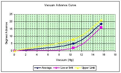
Vacuum advance calibrations are different between stock engines and modified engines, especially if you have a lot of cam and have relatively low manifold vacuum at idle. Most stock vacuum advance cans aren?t fully-deployed until they see about 15? Hg. Manifold vacuum, so those cans don?t work very well on a modified engine; with less than 15? Hg. at a rough idle, the stock can will ?dither? in and out in response to the rapidly-changing manifold vacuum, constantly varying the amount of vacuum advance, which creates an unstable idle. Modified engines with more cam that generate less than 15? Hg. of vacuum at idle need a vacuum advance can that?s fully-deployed at least 1?, preferably 2? of vacuum less than idle vacuum level so idle advance is solid and stable; the Echlin #VC-1810 advance can (about $10 at NAPA) provides the same amount of advance as the stock can (15 degrees), but is fully-deployed at only 8? of vacuum, so there is no variation in idle timing even with a stout cam.
For peak engine performance, driveability, idle cooling and efficiency in a street-driven car, you need vacuum advance, connected to full manifold vacuum. Absolutely. Positively. Don't ask Summit or Jeg's about it ? they don?t understand it, they're on commission, and they want to sell "race car" parts.
From the Edelbrock Performer and Thunder Series AVS Carburetor Owners Manual:
Despite the enormous variety in engine designs, virtually all (spark-ignition 4-Cycle) engines have very similar A/F Ratio requirements. For fully warmed-up engines, the range of A/F is:
| A/F RATIO | CHARACTERISTICS | TYPICAL A/F RATIOS |
|---|---|---|
| 5 to 1 | RICH BURN LIMIT: Combustion is weak/erratic. |
|
| 6-9 to 1 | EXTREMELY RICH: Black smoke and low power. | |
| 10-11 to 1 | VERY RICH: Some supercharged engines run in this range at full power as a means of controlling detonation. | |
| 12-13 to 1 | RICH: Best power A/F: Un-supercharged WOT. | |
| 14-15 to 1 | CHEMICALLY IDEAL: At 14.6 the A/F is at the theoretical ideal ratio with no excess fuel or oxygen after combustion. Good A/F for part throttle cruise and light to moderate acceleration. | |
| 16-17 to 1 | LEAN: Best economy A/F ratio. Borderline for part throttle drivability (worse than borderline if EGR is used). | |
| 18-19 to 1 | VERY LEAN: Usual lean limit (Driveability). | |
| 20-25 to 1 | LEAN BURN LEAN: Varies with engine and system. |
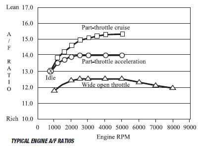
Even though engines will run anywhere between 5 and 25 A/F, the usual target values for an un-supercharged engine are a fairly narrow range (Figure 1). A/F is about 12.5 for the WOT and 14.0-15.5 at part-throttle cruise. An intermediate value of about 13.5-14.0 is usually used for mid-range power (non-WOT acceleration).
Ignition System
In order to utilize precision A/F mixtures, the ignition system must produce a high voltage spark at just the right moment so maximum work is extracted from the explosive charge. Originally, the 440-3 engine was developed for use in the oil fields where they could chug steadily along at say 2100 RPM. In that situation, you could set the timing for that one speed and load and forget everything else. A vehicle however, is subjected to different loads and RPMs which result in the need for variable timing requirements. These timing requirements are established by two separate functions in a distributor. The first is centrifugal advance which is used to ensure maximum power can be produced throughout the normal operational RPM range of the engine. The second system is vacuum advance which is primarily used to maximize fuel economy. Problems in either advance system will create drivability problems (detonation, pinging, poor performance, overheating, etc.).
Centrifugal (Mechanical) Advance
For the A/F mixture to burn efficiently as the engine RPM increases, the ignition spark has to happen sooner (measured in degrees before Top Dead Center). This requirement has to meet irregardless of engine load. The centrifugal advance system performs this function. The need to advance the timing stays constant up until about 3000 RPM. Additionally, the "Total Advance" must be limited to 34 degrees. Advancing the timing beyond these values can be detrimental to the engine. The term "Total Advance" refers to the sum total of initial plus centrifugal advance. If the spec says set the initial timing to 8 degrees then you can only have a maximum of 26 degrees centrifugal advance (8 + 26 = 34). The key thing to remember about centrifugal advance, is that it is directly related to engine RPM. Engine load (vacuum) has no effect on centrifugal advance.
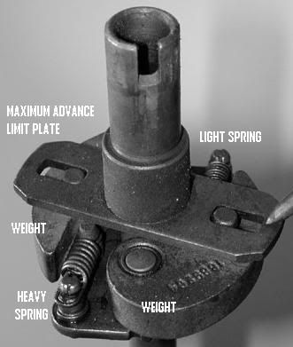
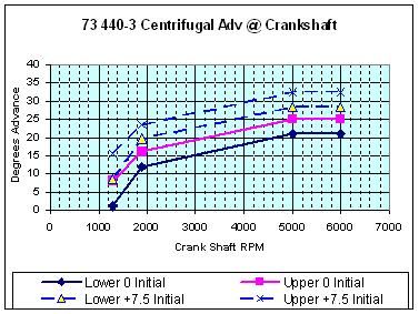
The centrifugal advance system uses rotating weights to vary the timing. As the weights are thrown outwards, the timing of the spark is advanced from the initial set point to around 34 degrees before TDC. The rate of change vs RPM curve is controlled by 2 springs. Lighter springs allow the weights to be thrown outwards faster thereby achieving maximum centrifugal advance faster. Heavier springs not only reduce the speed at which the weights are thrown outwards, they also can increase the RPM at which maximum centrifugal advance is achieved. Most street applications use 1 light and 1 heavy spring. This allows fast initial advance to some point and then a slower advance to the final RPM point. Advance curve specifications are typically listed in degrees of distributor RPM which for a 4 cycle engine is 1/2 crankshaft RPM. Make sure you translate your reading correctly. I am presenting the data here in crankshaft degrees unless otherwise noted. The Centrifugal Advance Spec curve for a MOPAR 440-3 MH chassis is shown below. The solid lines represent the listed Centrifugal Advance spec curve as seen at the crankshaft. The dashed lines represent the base Centrifugal Advance curve plus 8 degrees initial advance added in (Total Advance). Referring to the + 8 degree spec window (dashed lines), you can see that the small spring initially allows the advance to start around 650 RPM (9 to 16 degrees advance) and come up fast until you get 20 to 24 degrees advance @ 950 RPM. The heavy spring slows down the rate of change until a "Total Advance" of 29 to 33 degrees is achieved @ 2500 RPM (Total Advance). The actual advance curve of your stock MOPAR 440-3 MH distributor should fall somewhere between the dashed lines. As shown in the figure, the initial advance setting (i.e.: 8 degrees) affects the entire mechanical curve. For the 440-3 engine, the centrifugal advance curve basically stays the same over the years however, it can be tuned for maximum efficiency and power. I will be getting into that after I finish discussing the basics.
Note:
Computerized engines replace the centrifugal advance with a base timing lookup table (i.e. the timing curve).
The base value selected is still determined by engine RPM. That base value is then modified based on the
MAP sensor value which performs the same function as the vacuum advance can. This process is performed
several times a second.
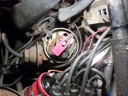
MOPAR Electronic Distributor
Note
Vacuum advance hose must be disconnected and plugged at carburetor in order to measure centrifugal
advance.
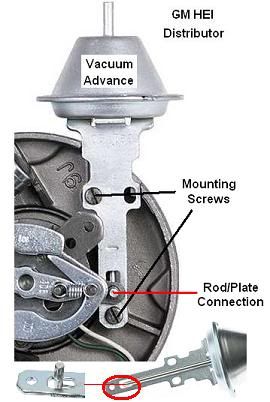
GM HEI Distributor
Vacuum Advance
From the mystery aspect, the vacuum advance circuit and the design changes surrounding it win hands down. The vacuum advance circuit is based on engine vacuum therefore this circuit is not even used when you put the pedal to the floor. At Wide-Open Throttle (WOT) engine vacuum drops to near 0Hg. For racing applications, you will typically discover that either the vacuum advance circuit is not there or has been disconnected. Racers are typically not concerned with economy (MPG) and drivability. What the vacuum advance circuit does do is provide up to 20 degrees more advance during idle or cruise operations. This improves both efficiency (MPG) and drivability which are two very important concerns for a motorhome application. Disconnecting the vacuum advance will also shorten plug life (carbon buildup).
It is important to understand that vacuum advance is placed on top of centrifugal advance.
If you are running at 2500 RPM with 32 degrees total advance (8 degrees initial + 26 degrees centrifugal) and engine vacuum is inducing a total of 20 degrees vacuum advance, the sum total of advance is 52 degrees. In the days of leaded gasoline, 52 degrees was the absolute maximum value of advance. On todays gasoline, a maximum value of 50 degrees should be utilized Anything greater is detrimental to the engine. The amount of vacuum advance change is dependent on engine loading. As you step on the pedal, engine vacuum drops therefore vacuum advance decreases. As you approach a steady speed on level ground, engine vacuum increases therefore vacuum advance increases. The changes in engine vacuum are also accompanied by a change in A/F mixtures by the carburetor. Richer mixtures (13/1) used for power reduce detonation (ping) whereas leaner mixtures (15/1) promote detonation (ping).
MOPAR Vacuum Advance
GM HEI Vacuum Advance
From Distributor Tuning and Theory Posting [Hotrodders Bulletin Board (HBB)]
Note:
The post at HBB is Chevy oriented. The principles are the same no matter what manufacturer produced the engine.
You will however find a lot of additional GM information in the post at HBB.
The vacuum advance control unit on the distributor is intended to advance the ignition timing above and beyond the limits of the mechanical advance (mechanical advance consists of the initial timing plus the centrifugal advance that the distributor adds as rpm comes up) under light to medium throttle settings. When the load on the engine is light or moderate, the timing can be advanced to improve fuel economy and throttle response. Once the engine load increases, this "over-advance" condition must be eliminated to produce peak power and to eliminate the possibility of detonation ("engine knock"). A control unit that responds to engine vacuum performs this job remarkably well.
Most stock engines will produce peak torque and power at wide open throttle with a total timing advance of 34 degrees. Also, under light load and steady-state cruise, an engine will accept a maximum timing advance of about 50 degrees. Once you advance the timing beyond this, the engine/car will start to "chug" or "jerk" at cruise due to the over-advanced timing condition. Anything less than 50 degrees produces less than optimum fuel economy at cruise speed.
The additional timing produced by the vacuum advance control unit must be tailored and matched to the engine and the distributors mechanical advance curve. The following considerations must be made when selecting a vacuum advance spec:
- How much engine vacuum is produced at cruise? If max vacuum at cruise is only 15 inches Hg, a vacuum advance control unit that needs 18 inches to peg out would be a poor selection.
- How much centrifugal advance ("total timing") is in effect at cruise rpm? If the distributor has very stiff centrifugal advance springs in it that allow maximum timing to only come in near red-line rpm, the vacuum advance control unit can be allowed to pull in more advance without the risk of exceeding the 50-degree maximum limit. If the engine has an advance curve that allows a full 34-degree mechanical advance at cruise rpm, the vacuum advance unit can only be allowed to pull in 14 more degrees of advance.
- Are you using "ported" or "manifold" vacuum to the distributor? "Ported" vacuum allows little or no vacuum to the distributor at idle. "Manifold" vacuum allows actual manifold vacuum to the distributor at all times.
If you have a racing engine, your engine may require additional timing advance at idle in order to idle properly. Radical cams will often require over 16 degrees of timing advance at idle in order to produce acceptable idle characteristics. If all of this initial advance is created by advancing the mechanical timing, the total mechanical advance may exceed the 34-degree limit by a significant margin. An appropriately selected vacuum advance unit, plugged into manifold vacuum, can provide the needed extra timing at idle to allow a fair idle, while maintaining maximum mechanical timing at 34. A tuning note on this: If you choose to run straight manifold vacuum to your vacuum advance in order to gain the additional timing advance at idle, you must select a vacuum advance control unit that pulls in all of the advance at a vacuum level 2" below (numerically less than) the manifold vacuum present at idle. If the vacuum advance control unit is not fully pulled in at idle, it will be somewhere in its mid-range, and it will fluctuate and vary the timing while the engine is idling. This will cause erratic timing with associated unstable idle rpm. A second tuning note on this: Advancing the timing at idle can assist in lowering engine temperatures. If you have an overheating problem at idle, and you have verified proper operation of your cooling system components, you can try running manifold vacuum to an appropriately selected vacuum advance unit as noted above. This will lower engine temps, but it will also increase hydrocarbon emissions on emission-controlled vehicles. Additionally, when you move from "ported" to "manifold", the idle RPM will increase. You will have to readjust the idle speed.
Thus, we see that there are many variables in the selection of an appropriate control unit. Yet, we should keep in mind that the control unit is somewhat of a "finesse" or "final tuning" aid to obtain a final, refined state of tune; we use it to just "tweak" the vehicle a little bit to provide that last little bit of optimization for drivability and economy. The vacuum advance unit is not used for primary tuning, nor does it have an effect on power or performance at wide open throttle.
With these general (and a little bit vague, I know...) concepts in mind, lets review a few concepts and terms. Then its on to the master listing of specs and parts...:
Starts @ "Hg
Vacuum is measured in "inches of Mercury". Mercury has the chemical symbol "Hg." Thus, manifold vacuum is
measured and referred to as "Hg". The "Start" spec for the control unit is a range of the minimum vacuum
required to get the control unit to just barely start moving. When selecting this specification, consideration
should be made to the amount of vacuum that a given engine produces, and what the load is on the engine
at this specification. For example, an engine with a very radical cam may be under very light load at 7
inches Hg, and can tolerate a little vacuum advance at this load level. Your moms Caprice, on the other
hand, has such a mild cam that you dont want the vacuum to start coming in until 9 - 10 inches Hg. For
most street driven vehicle performance applications, starting the vacuum advance at about 8" Hg produces
good results.
Since the vacuum advance control unit is a part of the distributor, the number of degrees of vacuum advance is specified in DISTRIBUTOR degrees - NOT crankshaft degrees. When talking about these control units, it is important that you know whether the person youre talking to is referring to the distributor degrees, or if hes talking crankshaft degrees. All of the listings shown in the following chart, and in any shop manual & technical spec sheet, will refer to distributor degrees of vacuum advance. You must DOUBLE this number to obtain crankshaft degrees (which is what you "see" with your timing light). Thus, a vacuum advance control unit with 8 degrees of maximum advance produces 16 degrees of ignition advance in relationship to the crankshaft. When selecting a unit for max advance spec, the total centrifugal timing at cruise must be considered. Thus, a car set up to produce 36 degrees of total mechanical advance at 2500 rpm needs a vacuum advance control unit producing 16 degrees of crankshaft advance. This would be an 8-degree vacuum advance control unit.
Max Advance @ "Hg
This is the range of manifold vacuum at which the maximum vacuum advance is pegged out. In selecting this
specification, you must consider the vacuum produced at cruise speed and light throttle application. If your
engine never produces 20" Hg, you better not select a control unit requiring 21" Hg to work.
Prior to 1972, most vehicles had the distributor vacuum advance connected to a manifold vacuum port. With this configuration, you applied full vacuum to the distributor vacuum advance at idle. This meant you had around 20 degrees additional advance above the initial setting applied at idle. When setting your timing and adjusting the carburetor idle mixture, you removed this extra advance by disconnecting and plugging the vacuum hose from the carburetor before doing adjustments. This works well for the racing crowd which needs the extra advance for the larger cams. In 1972, in order to meet tightening emissions requirements, manufactures moved the vacuum advance hose to what is commonly referred to as a ported vacuum port. This port is located just above the throttle plate and does not see engine vacuum at idle. With no vacuum applied at idle, there is no vacuum advance being introduced at the distributor. This allows the engine to run hotter at idle and burn NOx more efficiently. Once the throttle is cracked open, full manifold vacuum is seen at the ported vacuum port and vacuum advance operation from that point is the same as it was prior to 1972. Most performance tuning descriptions (aftermarket tech reps) will tell you to move the vacuum advance hose to the manifold vacuum port and plug the ported vacuum port. The only real adverse impact to doing this is that you may fail an emissions check. However what they neglect to tell you is it also means that you will need to modify your initial timing and carburetor idle screw adjustments methods (factory settings will no longer apply).
When moving to manifold vacuum advance, the critical issues are:
- Total advance cannot exceed 50 degrees (Initial advance + Centrifugal Advance + Vacuum Advance)
- All Vacuum advance must be implemented by 2Hg below maximum manifold vacuum (In drive for automatics). Failure to do this will cause the idle RPM to fluctuate due to manifold vacuum variations.
- Initial vacuum advance starting point has to be adjusted such that it does not produce pinging.
While this seems daunting, it is all addressed in the procedures below. A side benefit of using the manifold vacuum port is the engine will run cooler.
Along comes 1975 and MOPAR implements Exhaust Gas Recirculation (EGR). From the distributor stand point, nothing much changed however the carburetors changed some and now a small percentage of burned exhaust mixture is being introduced into the intake mixture. The purpose is to reduce combustion temperatures during part throttle (cruise) conditions which in turn reduces NOx emissions. Unfortunately diluting the A/F mixture also robs the engine of power. Additionally, the EGR valve can get clogged up and stick resulting in a large vacuum leak. Make sure you check it if installed. Operation of the EGR circuit is a bit complicated but it basically applies a small venturi (not manifold) vacuum control signal from the carburetor to a vacuum amplifier on the rear of the engine. The vacuum amplifier amplifies the signal and controls the EGR valve via a heat operated sensor valve located by the thermostat. The sensor valve prevents EGR valve operation while the engine is warming up. When an EGR based system is utilized (not disconnected), maximum vacuum advance can be increase to allow up to 56 degrees (initial + mechanical + vacuum).
Along comes 1977 and as a cost cutting measure (remember the first Chrysler Bankruptcy in 1979?), MOPAR does something real dumb to the 440-3. In order to meet tightening emissions requirements, rather than redesign the heads for greater efficiency, MOPAR drops the pistons down and reduces the compression ratio. This robs the engine of more power. [b]Many people end up driving themselves nuts[/b] trying to squeeze more power from the engine wondering why it is not as powerful as 76 and earlier engines. Naturally they blame emissions control systems but the drop in compression ratio is the real culprit. Sadly, MOPAR stops producing a motorhome chassis in 1979.
Tuning Tools
Note:
Tools listed here are for example. Equivalent brands can be used instead.
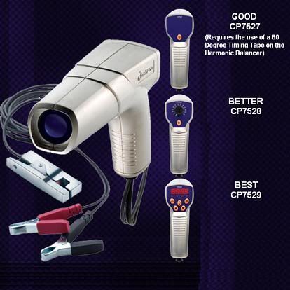
Timing LightTiming lights come in Good, Better and Best Categories.
|
|
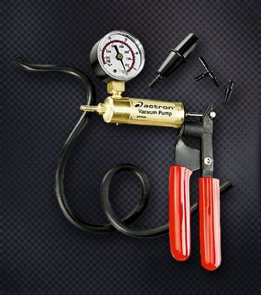
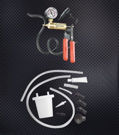
Hand Operated Vacuum Pump
|
|
|
|
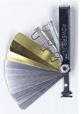
Feeler Gauge - Steel and Non-Magnetic (Brass) Blades
|
|
Lock Ring Pliers
|
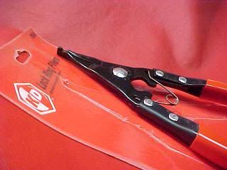
|
Vacuum Gauge
|
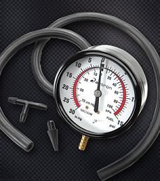
|
Wideband A/F Meter
|
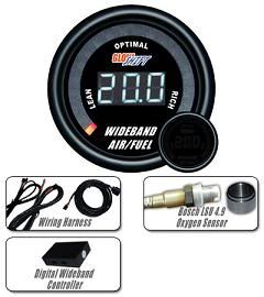
|
Ignition Setup
Baselining
Verifing Timing Chain
The distributor is driven by the cam. Given that the distributor is adjustable you can compensate retarded ignition timing due to chain wear however, the cam is not adjustable. Most manufactures used nylon toothed cam gears which wear faster than steel ones. If excessive chain assembly wear is discovered then even though both gears must be replaced, it is advisable to replace the chain assembly with a double-row timing set. A double-row timing set is longer lasting than a normal timing set. If chain slack is severe, then the chain can jump a tooth which can also result in 1 or more bent valves. Ford 460 and the Dodge 360 owners should be aware that these 2 engines can exhibit excessive slack within 40,000 miles. The following procedure can easily be performed when you change plugs however it should initially be done at 20,000 miles from new or replacement and every 10,000 miles thereafter.
- Remove the spark plugs and distributor cap.
- Using a socket and long handled ratchet on the harmonic balancer bolt, turn the crankshaft clockwise until the timing mark is aligned with the TDC mark. Do not reverse direction to align the marks. If need be, go all the way around again.
- Use a piece of tape or other material to form a precise reference point between the distributor body and the rotor.
- While closely watching the reference point on the distributor and rotor (enlist an assistant if necessary), turn the crankshaft in the opposite direction (counter clockwise) very slowly until the rotor just begins to move.
- The difference from TDC to the current position of the harmonic balancer mark represents chain slack in degrees. If the value is greater than 9 degrees, then the chain assembly should be replaced. Values of 15 degrees or more can result in the chain slipping a tooth.
Measuring Existing Centrifugal Advance Curve
From Timing is everything [MoPar Muscle Magazine April 98 Article]
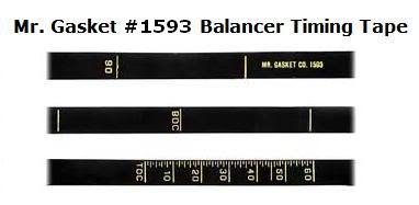
- Setting out to modify the advance curve without knowing what you've got is like picking up a date in a smoky Vegas lounge at closing time. The modifications may work out, but you might be disappointed with what you end up with. You need to check the RPM at which the centrifugal advance begins to kick in, how much it advances for an incremental RPM increase and at what RPM it has finished advancing or is "all in." To do this, you need only a timing light, tach and degreed damper. Mark the damper yourself as described in the MoPar Engine Book or stick on the MoPar Performance timing tape. Use graph paper to plot the point to generate a nifty looking curve. It will give you something to hang on your fridge besides your three-year olds artwork.
- With a marked damper: the timing can be read up to 60К using the -0- mark on the timing tab as a reference.
- With a dial back timing light, the timing offset can be read off the dial or digital readout referenced to the -0- mark on the timing tab.
- Disconnect and block the vacuum advance and read the timing at idle. Bump up the RPM while reading the timing until the advance just begins to kick in. Record the RPM. If it's right off idle speed, try backing down the idle and start again.
- Note: Centrifugal advance on a most stock engines does not start until at least 1000 RPM.
- Continue to increase the RPM in even steps of 500 rpm, recording the timing until it no longer advances. Zero in on the exact RPM at which the timing is "all in." Subtract the initial timing and you've got the centrifugal advance curve. The total timing reading at maximum advance minus the initial advance is the total amount of centrifugal advance, or how much is "in the plate." If you're mathematically challenged like us, you can set the initial timing at TDC and read the centrifugal curve directly without having to subtract the initial setting.
Measuring Existing Vacuum Advance Curve
As with centrifugal advance, to tune vacuum advance requires its curve be mapped. Again, this can be done with the engine used as the distributor machine, only this time using a hand vacuum pump to check the rate of advance for various vacuum levels. The procedure is simple enough: Pull up vacuum with the hand pump while checking the timing. Note the vacuum pump's gauge point where the advance just begins to kick in and record this. Move the vacuum level up in 1 inch increments, recording the vacuum level and how much the timing has correspondingly been increased. There's a trick here: Lower the idle speed to well below the RPM at which the centrifugal advance kicks in each time the vacuum pump level is pulled up. Otherwise, as the vacuum advance brings up the timing, the RPM will increase causing the centrifugal advance to come into play and invalidating your readings.
| Year/Engine | Distributor | Cap | Rotor | Points | Elec Ign Pick-up |
Advance | Coil | Balance Resistor |
Ign Module (ECM) |
|---|---|---|---|---|---|---|---|---|---|
| 1969-71 318 (w/o Elec Ign) |
2875805 | 2444507 Echlin MO20 |
1838516 Echlin MO13 |
2098244 Echlin CS851 |
N/A | 2875806 | 2495531 Echlin IC12 |
2275590 Echlin ICR12/ICR13 |
N/A |
| 1972 318 (w/o Elec Ign) |
3656295 | 2444507 Echlin MO20 |
1838516 Echlin MO13 |
2098244 Echlin CS851 |
N/A | 3438424 Echlin VC3008 |
2495531 Echlin IC12 |
2275590 Echlin ICR12/ICR13 |
N/A |
| 1969-77 318 (with Elec Ign; w/o ERS) |
3656686 | 2444507 Echlin MO20 |
1838516 Echlin MO13 |
N/A | 3656738 Echlin MP804 |
3656682 | 2495531 Echlin IC12 |
3656199 Echlin ICR24 |
3755550 Echlin TP50 |
| 1969-77 318 (with Elec Ign; with ERS) |
3656673 | 2444507 Echlin MO20 |
1838516 Echlin MO13 |
N/A | 3656738 Echlin MP804 |
3656766 Echlin VC3031 |
2495531 Echlin IC12 |
3656199 Echlin ICR24 |
3755550 Echlin TP50 |
| 1976 360 (with Elec Ign) |
3656673 | 2444507 Echlin MO20 |
1838516 Echlin MO13 |
N/A | 3656738 Echlin MP804 |
3656766 Echlin VC3031 |
2495531 Echlin IC12 |
3656199 Echlin ICR24 |
3755550 Echlin TP50 |
| 1970-71 413 (w/o Elec Ign) |
2875986 | 2444507 Echlin MO20 |
1838516 Echlin MO13 |
2098244 Echlin CS851 |
N/A | 2875768 | 2495531 Echlin IC12 |
2275590 Echlin ICR12/ICR13 |
N/A |
| 1972 413 (w/o Elec Ign) |
3656366 | 2444507 Echlin MO20 |
1838516 Echlin MO13 |
2098244 Echlin CS851 |
N/A | 2875768 | 2495531 Echlin IC12 |
2275590 Echlin ICR12/ICR13 |
N/A |
| 1973 413 (w/o Elec Ign) |
3656835 | 2444507 Echlin MO20 |
1838516 Echlin MO13 |
2098244 Echlin CS851 |
N/A | 3656828 | 2495531 Echlin IC12 |
2275590 Echlin ICR12/ICR13 |
N/A |
| 1972 413 (with Elec Ign) |
3656686 | 2444507 Echlin MO20 |
1838516 Echlin MO13 |
N/A | 3656738 Echlin MP804 |
3656682 | 2495531 Echlin IC12 |
3656199 Echlin ICR24 |
3755550 Echlin TP50 |
| 1973 413 (with Elec Ign) |
3656840 | 2444507 Echlin MO20 |
1838516 Echlin MO13 |
N/A | 3656738 Echlin MP804 |
3656833 | 2495531 Echlin IC12 |
3656199 Echlin ICR24 |
3755550 Echlin TP50 |
| 1971-76 440 (with Elec Ign) |
3656158 | 2444507 Echlin MO20 |
1838516 Echlin MO13 |
N/A | 3656738 Echlin MP804 |
3656310 Echlin VC3028 |
2495531 Echlin IC12 |
3656199 Echlin ICR24 |
3755550 Echlin TP50 |
| 1977 440 (with Elec Ign; w/o ERS) |
3755158 | 2444507 Echlin MO20 |
1838516 Echlin MO13 |
N/A | 3656738 Echlin MP804 |
3656310 Echlin VC3028 |
2495531 Echlin IC12 |
3656199 Echlin ICR24 |
3755550 Echlin TP50 |
| 1977 440 (with Elec Ign; with ERS) |
3755888 | 2444507 Echlin MO20 |
1838516 Echlin MO13 |
N/A | 3656738 Echlin MP804 |
3874891 | 2495531 Echlin IC12 |
3656199 Echlin ICR24 |
3755550 Echlin TP50 |
| System Test | |||||||||