Dave's Place
Power Supply Board (838 and 8310)
Before attempting any repairs or testing, check out the electrical safety pages.

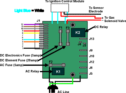
The Power Supply Boards for the 838 and 8310 (after the last recall) come in two versions: two way (120 volt and gas) and three way (120 volt, 12 volt, and gas). The only difference is the two way version doesn't have the DC components and terminals that the three way model does. The graphic below represents the three way version.
The Power Supply Board (also sometimes referred to as the Interface Board) is the central point for all things electronic on the refrigerator. All electrical input and output pass through it. Both 120 volt and 12 volt power connect to the refrigerator at the board. The board tells the Ignition Control Module to light the burner when appropriate and also provides the power for both the AC (120 volt) element and the DC (12 volt) element. The user controls the Power Supply Board by making selections at the eyebrow, which sends signals to the board via the J1 plug.
As you can tell by the graphic above, the three way board has three fuses (the two way board only two): a 20 amp fuse (F3) for the 12 volt DC element and DC relay (absent on the two way board), a 3 amp fuse (F1) for all the electronic controls including the interior light and high humidity switch, and a 5 amp fuse (F2) for the 120 volt AC element and circuitry. This last fuse has burned out many a 12 volt test light by someone accidentally testing the fuse with it. The AC fuse, part of the AC relay, and the J5 and J6 terminals are 120 volt components. Everything else is 12 volt. If you have a continual problem with the 3 amp (electronics) fuse, a likely culprit is a corroded and shorting interior light.
Troubleshooting
Troubleshooting the Power Supply Board is relatively simple. It's a matter of testing the board
for the correct input and output in a given situation, using the tables below. If the input for
a situation is correct but the output isn't, then the board is bad, assuming all fuses and
connections are good. As an example: If the AC heat element were not getting hot, you would first
check the J5 and J6 terminals for 120 volt across them. If 120 volt were present, the heat
element would be bad. If 120 volt were not present, then you would have to look further. You
would then check the AC circuitry and fuse for the presence of 120 volt with a 120 volt meter
by using the J5 terminal as the common test point and testing for voltage on both sides of the
fuse with the other test probe. If these were good, then you would test the orange wire (J1-4)
on the J1 plug for the presence of 12 volt(+). The eyebrow "tells" the Power Supply to switch
to AC mode by signaling it with 12 volt(+) at the J1-4 terminal (orange wire). At this point,
after the preceding tests, if 12 volt(+) were present at the J1-4 terminal, the Power Supply
Board would be bad.
J1 connections table:

| Violet (J1-12) | 12 volt(+) when DC selected on three way models |
| Tan (J1-11) | 12 volt(+) when Gas selected |
| Gray (J1-10) | Ground (-) for Gas and DC lights |
| Red (J1-9) | To eyebrow Check light |
| Yellow (J1-8) | 12 volt (+) for eyebrow lights |
| Blank | |
| Blank | |
| White (J1-5) | Ground for (-) AC light |
| Orange (J1-4) | 12 volt(+) when AC selected |
| Blank | |
| Blank | |
| Black (J1-1) | 12 volt(+) to thermostat and eventually to eyebrow switches for heat selection |
Other connections table:
| J3 | 12 volt(-) for interior light and high humidity element |
| J4 | 12 volt(+) for interior light and high humidity element |
| J5 | 120 volt (common) to AC heat element |
| J6 | 120 volt (line) to AC heat element |
| J9 | 12 volt(+) supply from RV |
| J10 | 12 volt(-) supply from RV |
| J12 | 12 volt(-) to DC heat element |
| J13 | 12 volt(+) to DC heat element |
You can find the actual wiring diagrams in the Library.
See the Ignition Control Module page for the connection to that component.
Norcold Electronics (838 and 8310) Home
RV Refrigerator Home
This RV refridgerator information was originally located on rvmobile.comRV Mobile Inc. 11715 HWY 99, Everett, WA 98204
The owner of RV Mobile Inc. apparently suffered a heart attack and the original website was shut down.
It has been reposted here to preserve this wealth of information RV refridgerator information.